
Chalcopyrite solar cell

a solar cell and chalcopyrite technology, applied in the field of solar cells, can solve the problems of inability to introduce a scribing step using a metal needle, inability to manufacture cells having high conversion efficiency, and inability to adequately protect stainless steel substrates from hsub>, etc., and achieve the effect of high conversion efficiency

Inactive Publication Date: 2010-06-22
HONDA MOTOR CO LTD
View PDF26 Cites 59 Cited by
  • Summary
  • Abstract
  • Description
  • Claims
  • Application Information

AI Technical Summary

Benefits of technology

[0017]As described above, the conventional techniques do not use a substrate material that satisfies requirements that the material is a high insulation material, is easily available, is relatively inexpensive and has high adhesion to the Mo electrode layer (lower electrode thin film), a smooth surface, a melting point equal to or higher than 600 degrees C., a small thickness, a light weight and high flexibility.
[0028]The binder made of a nitride-based material is relatively expensive in itself. In addition, the inexpensive ceramic-based material used for the intermediate layer allows reduction of the thickness of the binder layer. Thus, compared with the conventional chalcopyrite solar cell having a glass substrate, the chalcopyrite solar cell according to the present invention can be manufactured at low cost.

Problems solved by technology

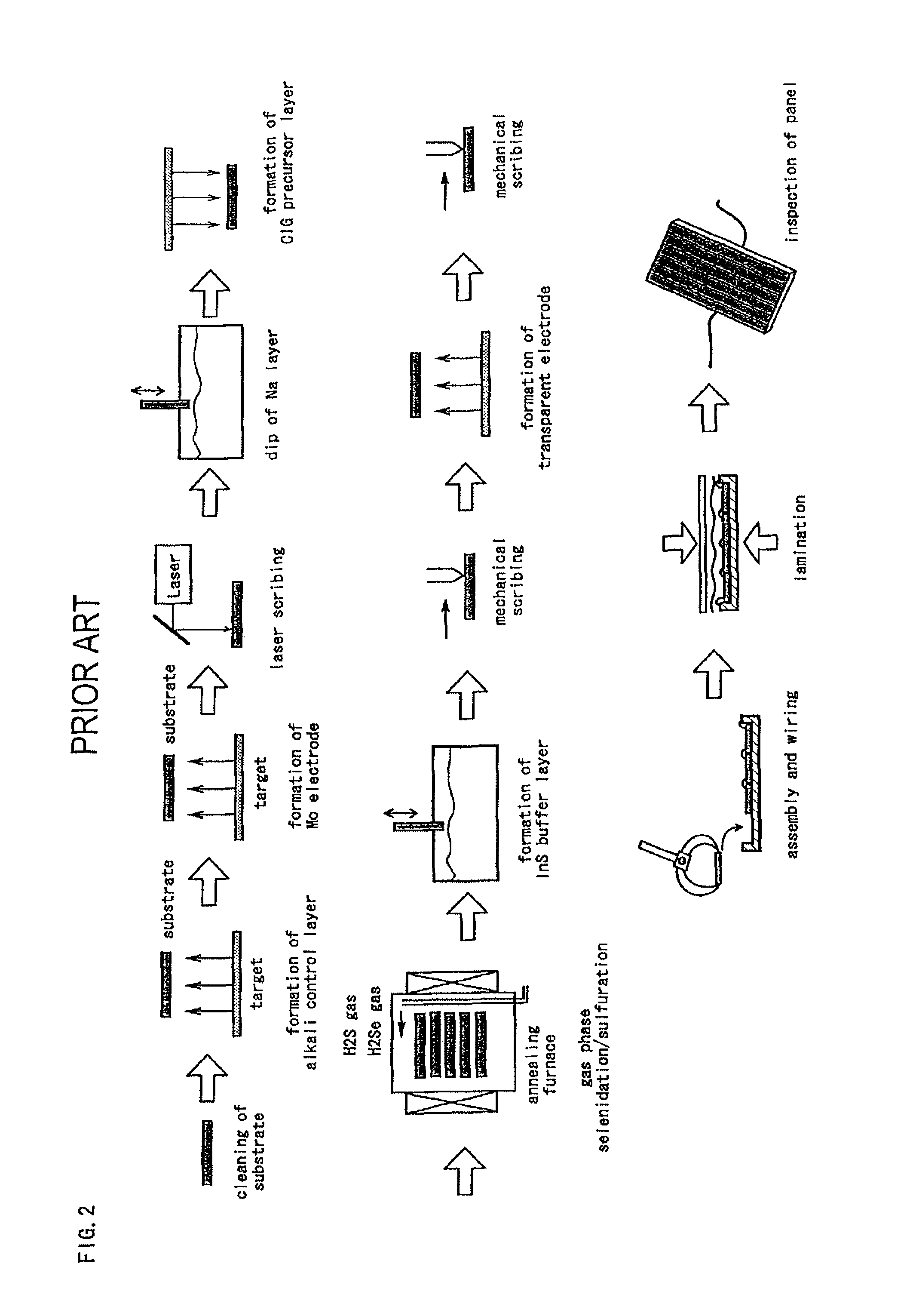
Thus, a high-temperature process carried out at a temperature higher than 500 degrees C., such as the gas phase selenidation process, cannot be used, and as a result, a cell having high conversion efficiency cannot be manufactured.
The technique of forming a silicon oxide or ferric fluoride layer (protective layer) on the upper and lower surfaces of a stainless steel substrate disclosed in the patent literature 2 has a disadvantage that the stainless steel substrate cannot be adequately protected against H2Se gas in the gas phase selenidation step, and a Mo electrode layer (a back-side electrode thin film) peels off the corroded stainless steel substrate.
In addition, since the conductive stainless steel substrate is exposed when the protective layer peels off, a scribing step using a metal needle cannot be introduced.
Furthermore, although various kinds of substrate materials are listed in the patent literature 3, all the techniques described as complete examples in the description of the embodiments of the patent literature use a glass substrate, and the other substrate materials listed in the patent literature are not described in detail enough for those skilled in the art to apply those materials to the techniques.
For example, in the examples described in the patent literature, the substrate is annealed at temperatures ranging from 385 to 495 degrees C. However, these temperatures are intended only for soda lime glass, and there remains a doubt whether the same process can be applied to the other substrate materials listed in the patent literature.

Method used


Image

  • Chalcopyrite solar cell
  • Chalcopyrite solar cell
  • Chalcopyrite solar cell

Examples


Embodiment Construction

[0038]Prior to describing an embodiment of the present invention, a surface configuration of a laminated mica substrate will be described. FIGS. 4(A) and 4(B) show results of measurement of the surface configuration of a laminated mica substrate at arbitrary two points. In FIGS. 4(A), 4(B), the abscissa indicates the horizontal position in the laminated mica substrate, and the ordinate indicates the vertical position. The laminated mica substrate is characterized in that the height varies very steeply, and the maximum height difference is large (in other words, the aspect ratio is high). As is apparent from FIGS. 4(A), 4(B), there is a maximum height difference of 5 to 6 μm in a horizontal range of several tens of micrometers. It can be considered that the large height difference is due to the method of manufacturing the laminated mica. Specifically, the laminated mica is manufactured by mixing pieces of pulverized mica with a resin. The pieces of pulverized mica exist on the surfac...


PUM

PropertyMeasurementUnit
thicknessaaaaaaaaaa
thicknessaaaaaaaaaa
surface roughnessaaaaaaaaaa

Abstract

A chalcopyrite solar cell having a mica substrate or a laminated mica substrate, an intermediate layer made of a ceramic-based material formed on the mica substrate, and a binder layer formed on the intermediate layer. The intermediate layer has a thickness equal to or more than 2 μm and equal to or less than 20 μm. The binder layer has a thickness equal to or more than 3000 Å and equal to or less than 8000 Å. The intermediate layer and the binder layer are interposed between the mica substrate and a molybdenum electrode.

Description

TECHNICAL FIELD[0001]The present invention relates to a solar cell having a light absorbing layer made of a chalcopyrite compound. In particular, it relates to a solar cell having a substrate made of mica, which is flexible, or a material containing mica.BACKGROUND ART[0002]Solar cells, which receive light and convert the light into electric energy, are classified into the bulk type and the thin film type according to the thickness of the semiconductor. The thin-film solar cells have a semiconductor layer having a thickness equal to or less than several to several tens of micrometers and are classified into the Si thin film type and the compound thin film type. The compound thin film solar cells are further classified into several types including the II-VI family compound type and the chalcopyrite type, and some compound thin film solar cells have been commercially available. In particular, the chalcopyrite solar cell is referred to also as CIGS (Cu(InGa)Se) thin film solar cell, CI...

Claims


Application Information

Patent Timeline
Patent Type & Authority Patents(United States)
IPC IPC(8): H01L31/00
CPCH01L31/0322H01L31/0749H01L31/0392Y02E10/541H01L31/03925H01L31/03928
Inventor YONEZAWA, SATOSHI
Owner HONDA MOTOR CO LTD
Learn More