
Method and apparatus for improved high-speed adaptive equalization

a high-speed adaptive equalization and adaptive equalization technology, applied in pulse manipulation, pulse technique, instruments, etc., can solve the problems of difficult and costly implementation of such devices, limited component bandwidth, noise and bandwidth limitations of typical optical networks, etc., and achieve the effect of improving high-speed adaptive equalization

Inactive Publication Date: 2010-06-15
MICROSEMI STORAGE SOLUTIONS
View PDF4 Cites 2 Cited by
  • Summary
  • Abstract
  • Description
  • Claims
  • Application Information

AI Technical Summary

Benefits of technology

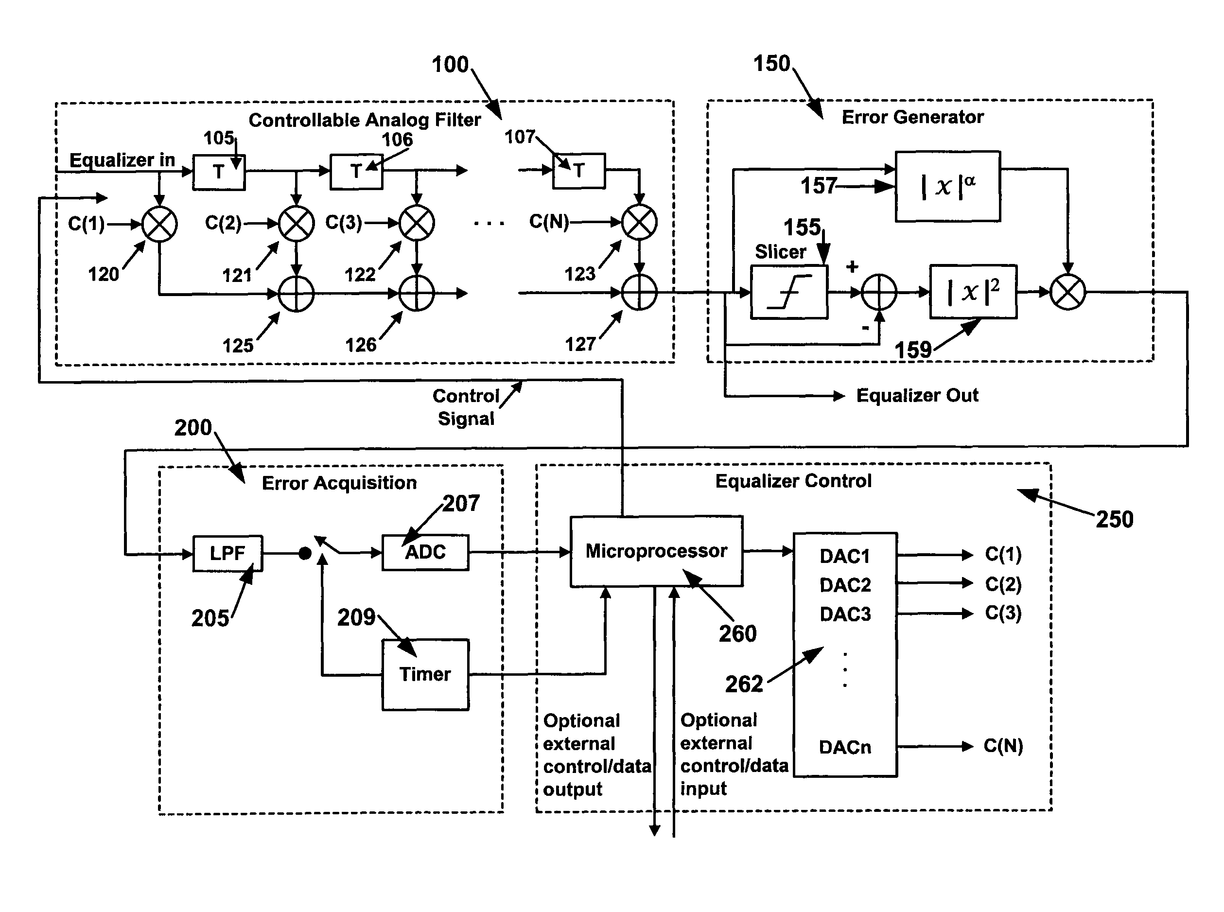
[0008]It is an object of the current invention to provide a method and apparatus for improved high-speed adaptive equalization that may operate effectively even in systems experiencing severe interference. By using one or more error generators and taking multiple samples across a bit interval, a preferred embodiment of the current invention may operate effectively when analyzing signals with severe interference. Advantageously, a preferred embodiment of the current invention may be deployed in a clockless configuration.
[0010]Optionally, one or more algorithms may be used to analyze the error data. For example, in some cases, a first algorithm may be used to assess error data and calculate a set of filter coefficients to provide an initial set of coefficients. The initial set of coefficients may be used to identify a coarse solution for alternate algorithms to use as a starting point. This enables the use of a wide variety of minimization algorithms to provide fine equalization even when multiple local minima exist. Typically, multi-dimensional minimization algorithms may be used.

Problems solved by technology

Typical optical networks are plagued by noise and bandwidth limitations such as polarization mode dispersion and limited component bandwidth.
However, the implementation of such devices has proven to be challenging and costly.
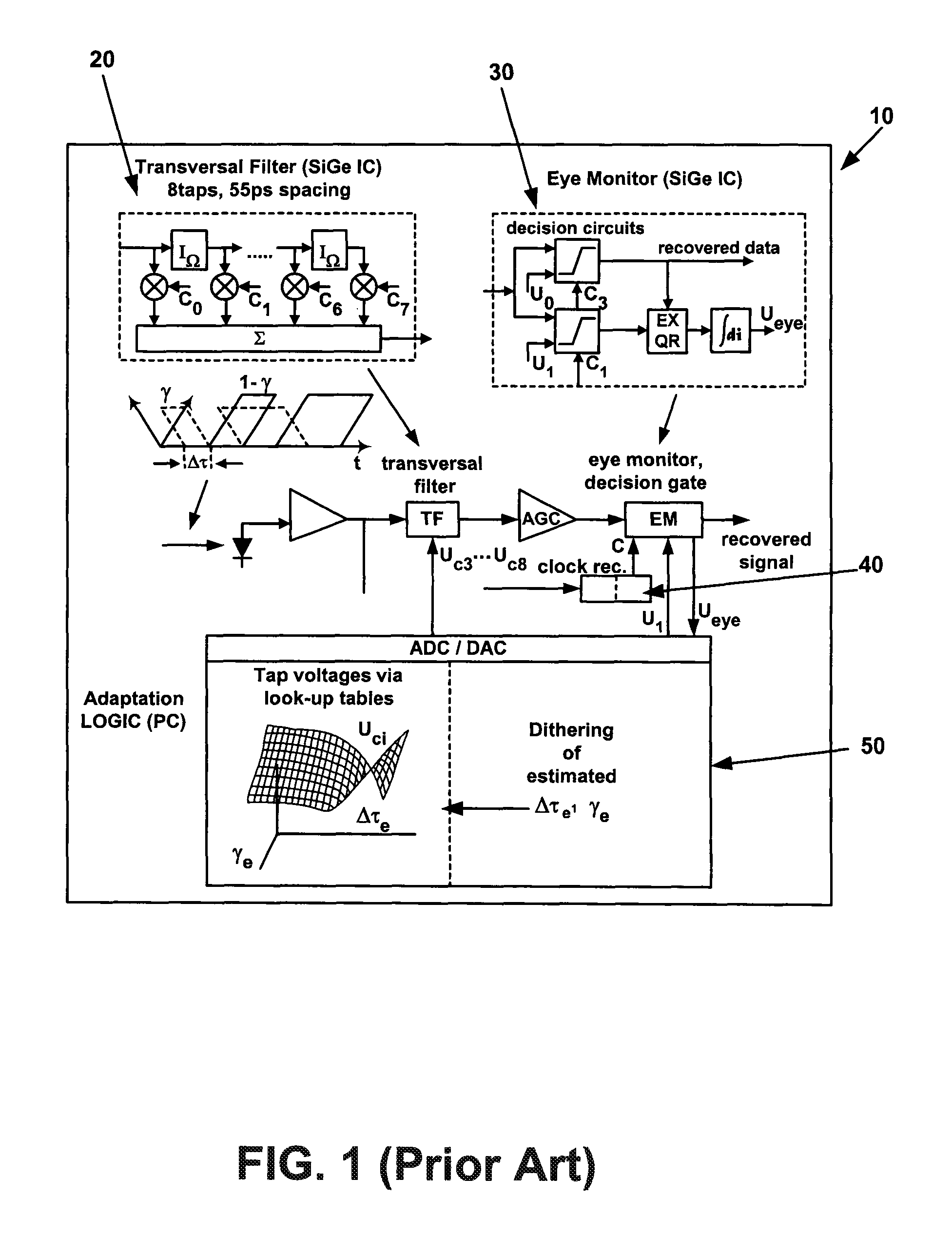
This type of design may fail in cases of severe distortion such as inter-symbol interference.
Typical eye monitors may fail in this situation.

Method used


Image

  • Method and apparatus for improved high-speed adaptive equalization
  • Method and apparatus for improved high-speed adaptive equalization
  • Method and apparatus for improved high-speed adaptive equalization

Examples


Embodiment Construction

[0020]FIG. 3 illustrates a preferred embodiment of the current invention 90. According to a preferred embodiment of the current invention, one or more data signals may be received by the controllable analog filter 100. Typically, the data signals may be analog, digital and / or sampled analog signals. Preferably, the one or more controllable analog filters serve to filter out noise and compensate for channel impairment or imperfections such as inter-symbol interference (ISI). In this example, a single controllable analog filter 100 is used. However, according to alternate embodiments of the current invention, one or more controllable analog filters may be used in various configurations. Furthermore, in some cases, a single controllable analog filter may comprise two or more filters. For example, FIG. 4 illustrates an example of a controllable analog filter 103 comprising two filters 110 and 112 implemented in a decision feedback equalizer (DFE) configuration according to an alternate ...


PUM


Abstract

A method and apparatus for improved high-speed adaptive equalization that may operate effectively even in systems experiencing severe interference by using one or more error generators and taking multiple samples across a bit interval. Advantageously, a preferred embodiment of the current invention may be deployed in a clockless configuration. Preferably, one or more controllable analog filters may be controlled by one or more microprocessors used to assess the error data from the error generators and to calculate the appropriate coefficients for the filters according to one or more error minimization algorithms. Preferably, the steps of sampling, assessment, calculation and coefficient setting may be done iteratively to converge to an optimum set of filter values and / or respond dynamically to signals with time-varying noise and interference characteristics.

Description

CROSS-REFERENCE TO RELATED APPLICATION[0001]The present application is a continuation application of U.S. patent application Ser. No. 09 / 955,278, filed Sep. 11, 2001, entitled “METHOD AND APPARATUS FOR IMPROVED HIGH-SPEED ADAPTIVE EQUALIZATION”, to issue on Nov. 27, 2007 as U.S. Pat. No. 7,301,997, the disclosure of which is incorporated herein by reference.BACKGROUND INFORMATION[0002]1. Field of the Invention[0003]The current invention relates to the field of signal equalization, particularly to enabling improved high-speed adaptive equalization.[0004]2. Description of Related Art[0005]Increased demand for high-speed communications services has required that economical and efficient new devices and techniques be developed to support performance increases. For example, as transmission rates climb to the 10-40 Gb / s range and beyond in modern optical networks, signal processing and conditioning techniques must be applied to filter out noise and reduce interference such as inter-symbol...

Claims


Application Information

Patent Timeline
Patent Type & Authority Patents(United States)
IPC IPC(8): H03H7/30H04B10/158
CPCH04B10/6971
Inventor WANG, JOHN S.BHOJA, SUDEEPPAVAN, SHANTHI
Owner MICROSEMI STORAGE SOLUTIONS
Learn More