
Shift register arrays

a technology of shift registers and arrays, applied in the field of shift registers, can solve the problems of increasing the cost of gate drivers, abnormal panel operation, shortening the operating life of transistors,

Active Publication Date: 2010-06-08
AU OPTRONICS CORP
View PDF9 Cites 10 Cited by
  • Summary
  • Abstract
  • Description
  • Claims
  • Application Information

AI Technical Summary

Benefits of technology

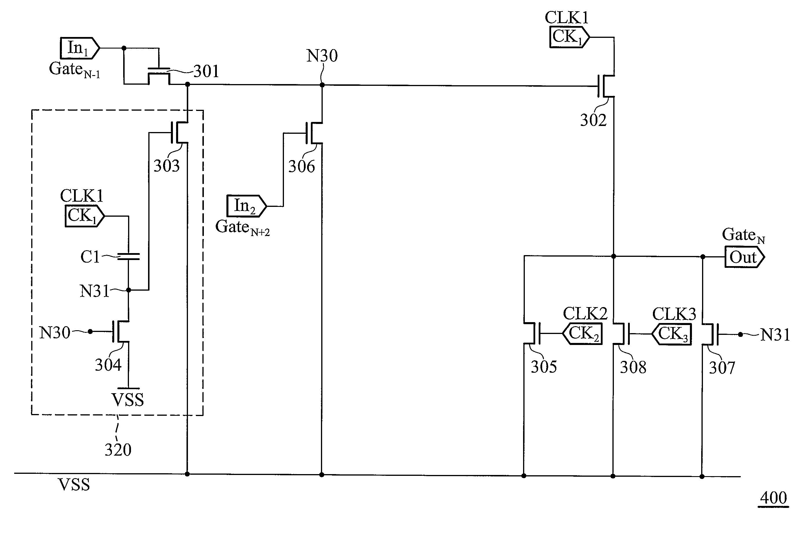
"The patent text describes a shift register array that includes multiple shift registers connected in series. Each shift register includes a first transistor, a second transistor, a pull-up unit, and a capacitor. The first transistor has a first gate, a first terminal, and a second terminal connected to a first node. The second transistor has a second gate, a third terminal, a first clock input terminal, and a fourth terminal connected to the output terminal. The pull-up unit includes a third transistor, a capacitor, and a fourth transistor. The third transistor has a third gate, a first clock input terminal, and a fourth terminal connected to the first node. The capacitor is connected between the first clock input terminal and the second node. The fourth transistor is connected between the second node and the ground and has a fourth gate connected to the first node. The shift register array can be used in various applications such as data transmission and synchronization."

Problems solved by technology

However, using gate drivers increases costs.
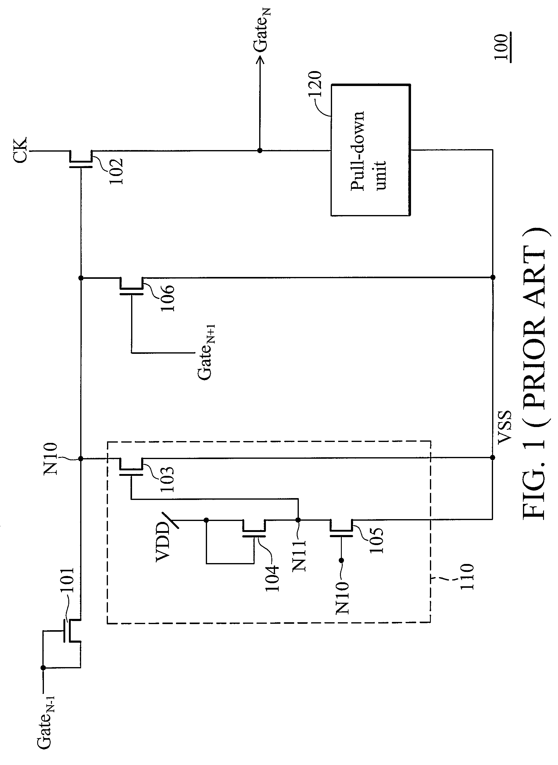
Therefore, given the above, for an AMLCD panel, the panel may abnormally operate due to stress problems of the shift registers after the panel is illuminated.
However, for the shift register 100, it does not matter if the gate pulse signal GateN−1 or the clock signal CK are active or not, the transistor 104 will always be turned on, thus shortening operating lifespan of the transistor 104 and possibly causing damage.

Method used


Image

  • Shift register arrays
  • Shift register arrays
  • Shift register arrays

Examples


Embodiment Construction

[0020]The following description is of the best-contemplated mode of carrying out the invention. This description is made for the purpose of illustrating the general principles of the invention and should not be taken in a limiting sense. The scope of the invention is best determined by reference to the appended claims.

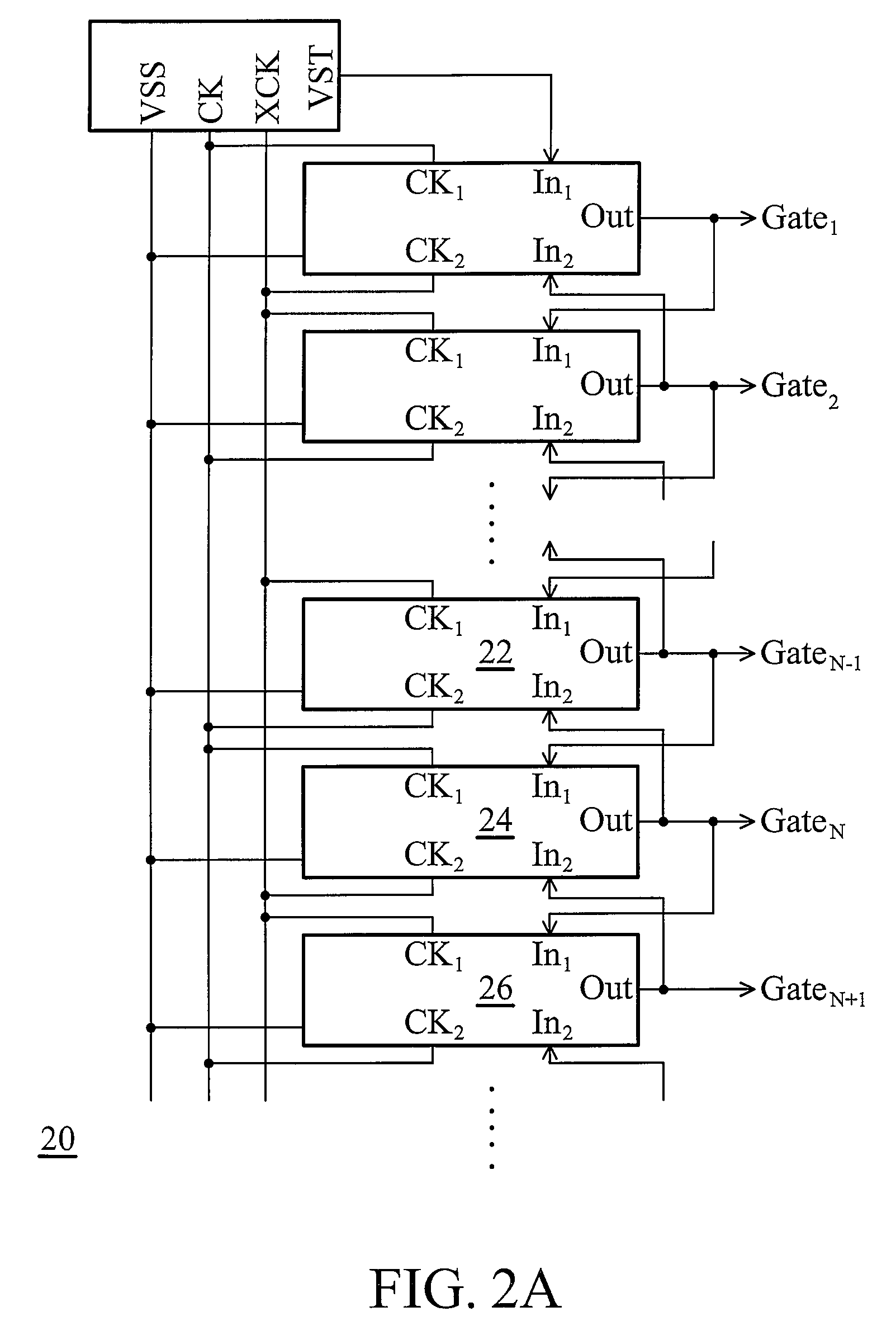
[0021]FIG. 2A shows a shift register array 20 according to an embodiment of the present invention. The shift register array 20 is composed of a plurality of shift registers connected in serial, wherein each shift register has the same circuit. A single shift register will be described in detail below. As shown in FIG. 2A, an input terminal In1 of a shift register 24 is coupled to an output terminal Out of a previous stage shift register 22 to receive a gate pulse signal GATEN−1, and an input terminal In2 of the shift register 24 is coupled to an output terminal Out of a next stage shift register 26 to receive a gate pulse signal GATEN+1. Moreover, an output terminal of...


PUM


Abstract

A shift register array is provided. The shift register array includes a plurality of shift registers connected in serial. The shift register includes a first transistor coupled between a first input terminal and a first node, a second transistor coupled between a first clock input terminal and an output terminal and a pull-up unit. The first transistor has a gate coupled to the first input terminal. The second transistor has a gate coupled to the first node. The pull-up unit includes a third transistor coupled between the first node and a ground, a capacitor coupled between the first clock input terminal and the second node and a fourth transistor coupled between the second node and the ground. The third transistor has a gate coupled to a second node. The fourth transistor has a gate coupled to the first node.

Description

CROSS REFERENCE TO RELATED APPLICATIONS[0001]This application claims priority of Taiwan Patent Application No. 096128973, filed on Aug. 7, 2007, the entirety of which is incorporated by reference herein.BACKGROUND OF THE INVENTION[0002]1. Field of the Invention[0003]The invention relates to a shift register, and more particularly to a shift register array of a liquid crystal display apparatus.[0004]2. Description of the Related Art[0005]At present, gate drivers and source drivers of most of the liquid crystal displays are disposed outside of the liquid crystal display panels, and are configured to generate gate pulse signals and data signals, respectively. However, using gate drivers increases costs. In order to reduce costs, the shift register arrays, which function as gate drivers, are fabricated on a glass substrate, i.e. an integrated driving circuit. An amorphous thin film transistor (TFT) process is often used in an active matrix liquid crystal display (AMLCD). Therefore, give...

Claims


Application Information

Patent Timeline
Patent Type & Authority Patents(United States)
IPC IPC(8): G11C19/00
CPCG11C19/28
Inventor CHIEN, CHIH-YUANKUO, YU-JUCHEN, WAN-JUNG
Owner AU OPTRONICS CORP
Learn More