
True angular catheter shaft deflection apparatus

a shaft deflection and angular catheter technology, applied in the field of catheters, can solve the problems of destroying or ablating a certain portion of the pathway, and the use of this type of catheter has limitations in reaching sites requiring active articulation during placement, and achieves the effect of removing significant variations in planarity during deflection

Inactive Publication Date: 2010-06-08
ST JUDE MEDICAL ATRIAL FIBRILLATION DIV
View PDF4 Cites 113 Cited by
  • Summary
  • Abstract
  • Description
  • Claims
  • Application Information

AI Technical Summary

Benefits of technology

The invention is a catheter with a distal section that can bend in multiple directions. The distal section is made of different materials with different hardness levels, creating a lumen and allowing for smooth bending. The softer material can be placed in a patterned way to provide asymmetrical bending. The catheter also includes pullwires and a system for actuation, as well as a component to prevent collapse of the distal section. The materials can be braided or co-extruded, among others. The technical effect is a catheter with improved flexibility and control during medical procedures.

Problems solved by technology

The resulting destruction of the cells eliminates their electrical conductivity, thus destroying, or ablating, a certain portion of the pathway.
Although perhaps useful for some more accessible sites, the use of this type of catheter has limitations in reaching sites requiring active articulation during placement.

Method used


Image

  • True angular catheter shaft deflection apparatus
  • True angular catheter shaft deflection apparatus
  • True angular catheter shaft deflection apparatus

Examples


Embodiment Construction

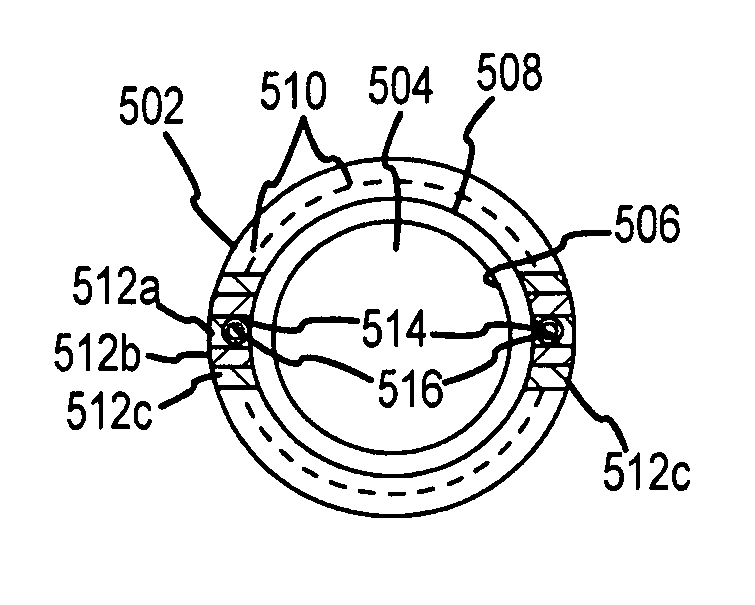
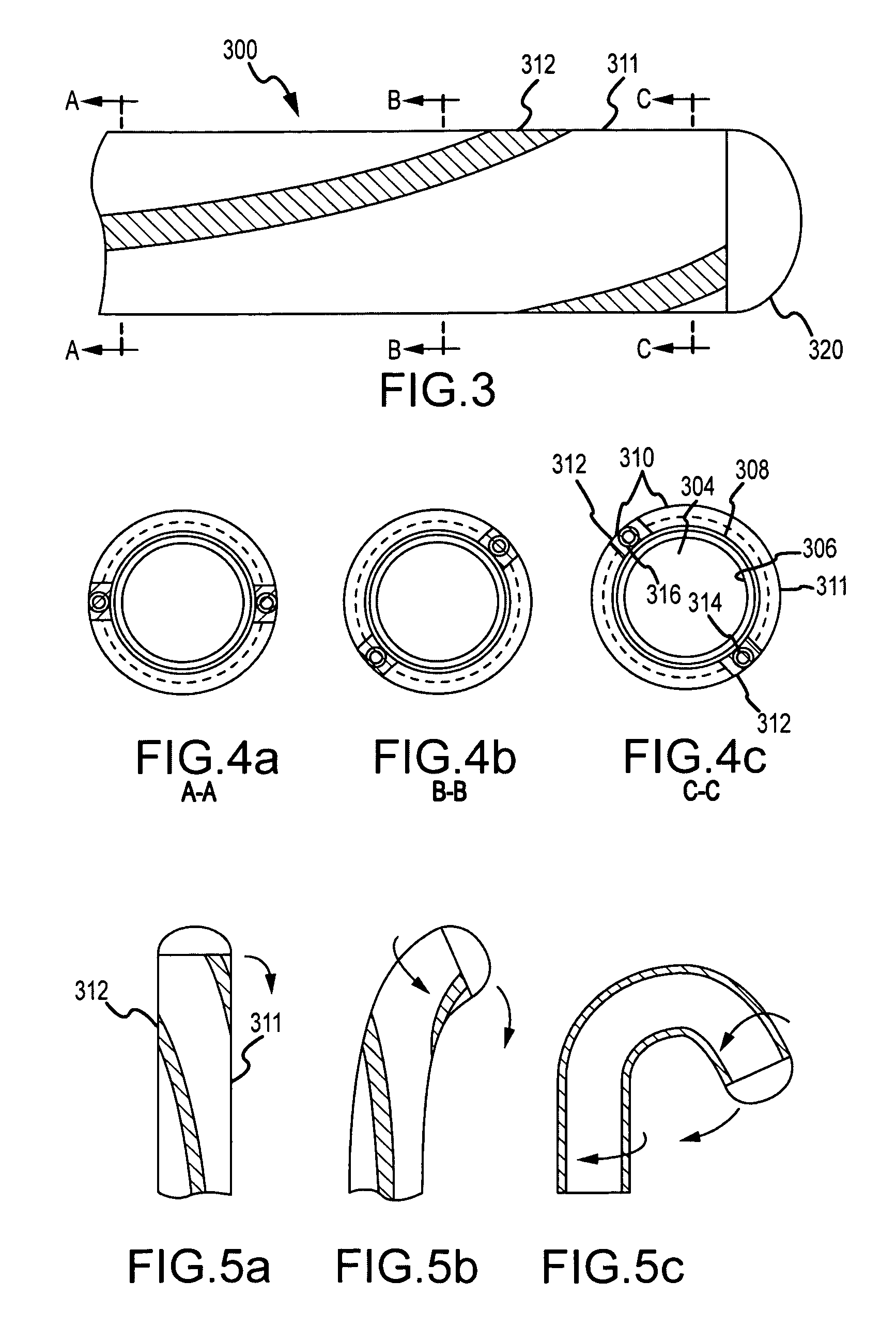
[0040]Several embodiments of a catheter distal tip deflection apparatus are depicted in the figures. As described further below, the catheter distal tip deflection apparatus according to the present invention provides a number of advantages, including, for example, reducing or eliminating significant variation in deflection path during shaft deflection, the ability to construct a catheter capable of a multitude of angular shaft deflection trajectories through a two or three dimensional range, improved product reliability, improved consistency and performance, and improved safety of electrophysiology ablation and diagnostic procedures.

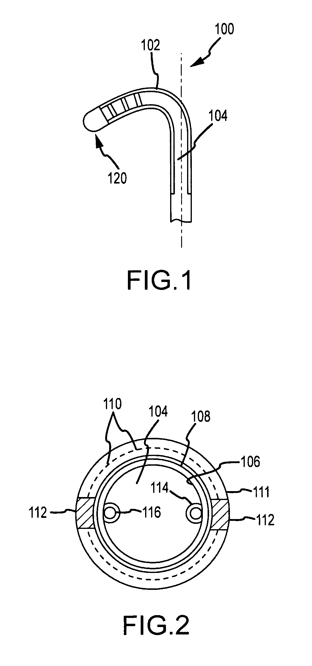
[0041]Referring to FIGS. 1 and 2, a single axis steerable catheter distal section 100 is disclosed in accordance with this invention. The catheter distal section 100 comprises a tubular body 102 defining a lumen or bore 104, and a tip electrode 120. As shown in FIG. 2, which is a transverse cross-sectional view of the tubular body 102, the tubular body ...


PUM


Abstract

The invention relates to a steerable catheter having a distal section with reduced variation in deflection path during deflection. The distal section of the catheter includes stripes of different material hardness along the length of the distal section affecting the directionality of catheter deflection upon the application of a deflection force like that applied by pull wires. The stripes result in preferential bending in a desired path with greater reproducibility.

Description

BACKGROUND OF THE INVENTION[0001]a. Field of the Invention[0002]The instant invention relates to catheters. In particular, the instant invention relates to a catheter with a steerable distal section having reduced variation in planarity during deflection.[0003]b. Background Art[0004]It is well-known that the pumping action of the heart is controlled by electrical stimulation of myocardial tissue. Stimulation of this tissue in various regions of the heart is controlled by a series of conduction pathways contained within the myocardial tissue.[0005]Cardiac arrhythmias arise when the pattern of the heartbeat is changed by abnormal impulse initiation or conduction in the myocardial tissue. Such disturbances often arise from additional conduction pathways which are present within the heart either from a congenital developmental abnormality or an acquired abnormality which changes the structure of the cardiac tissue, such as a myocardial infarction.[0006]One of the ways to treat such dist...

Claims


Application Information

Patent Timeline
Patent Type & Authority Patents(United States)
IPC IPC(8): A61M25/00
CPCA61M25/0041A61M25/005A61M25/008A61M25/0141A61M25/0147A61B2017/00106A61N1/056A61M2025/0081A61M2025/0161A61M25/0082
Inventor POTTER, DANIEL J.
Owner ST JUDE MEDICAL ATRIAL FIBRILLATION DIV
Learn More