Compact sliding sash lock

a sliding sash lock and compact technology, applied in the field of door and window hardware, can solve the problems of long-term adverse force against the secure joint of the latch device, the mechanical disadvantage of having to apply a large circular force to retract the locking bolt, and the lock structure is bulky and unappealing

Inactive Publication Date: 2010-06-08
YE JINTIAN
View PDF6 Cites 27 Cited by
  • Summary
  • Abstract
  • Description
  • Claims
  • Application Information

AI Technical Summary

Benefits of technology

[0009]In view of the foregoing, the object of the preset invention is to provide a compact sash lock that locks automatically and is squeezable directly over almost its entire body to actuate the release mechanism requiring no defecting actuators or handles.
[0010]Another object of the present invention is to provide a fail-safe locking mechanism for door and window sashes which is easy to manufacture.
[0013]A large button block extends laterally over the tubular posts of the base housing and has a beveled surface facing the cam surfaces of the plunger and two opposite end tunnels to fit snugly over the tubular posts for maintaining linear translations perpendicular to the moving direction of the plunger under an expansive bias for normally pushing the button block away from the base housing in cooperation with the biased counteraction of the cam surfaces of the plunger. The button block has a height greater than that of the surrounding walls of base housing. Then, a top housing is fastened to the base housing to enclose the plunger and button block allowing them to move within the respective ranges of translation.

Problems solved by technology

However, the lever needs a substantial projection from the main latch body taking up space upward as well as toward the user for the bolt to create a proper lever or bolt action inside the latch device.
This makes a bulky and unappealing lock structure that sticks into the viewing area of glass panes.
Under the superficial problem lies a mechanical disadvantage to have to apply a large circular force to retract a locking bolt out of engagement with the counterpart of the other sash.
However, such deflecting lever movements produce a long-term adverse force against the secure joint between the latch device and sash during their combined lifetime because normally there is only a couple of fasteners to endure the releasing depressions at repeated window openings.
Hence, there is need for a small form factor sash lock that is not only visually unobtrusive but also mechanically stable and ergonomically fit.

Method used


Image

  • Compact sliding sash lock
  • Compact sliding sash lock
  • Compact sliding sash lock

Examples


Embodiment Construction

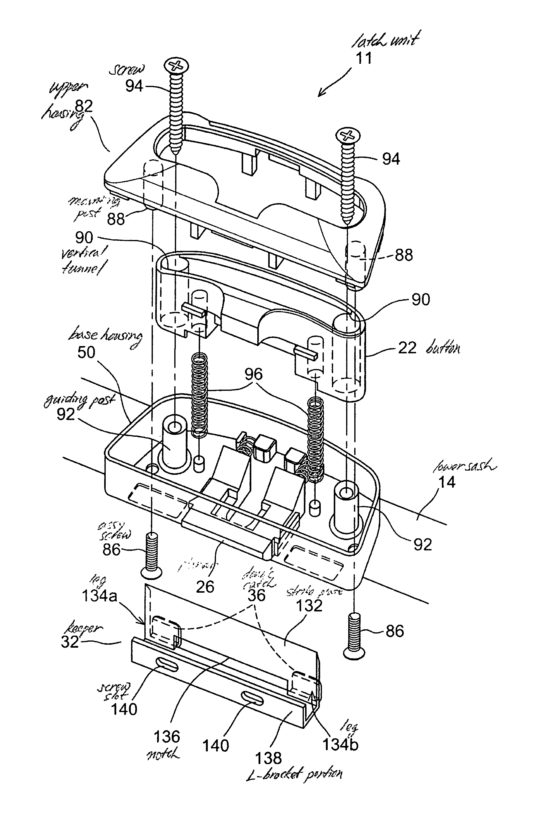
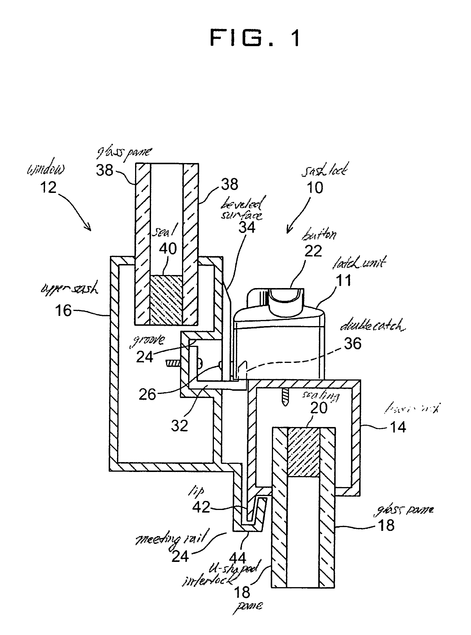
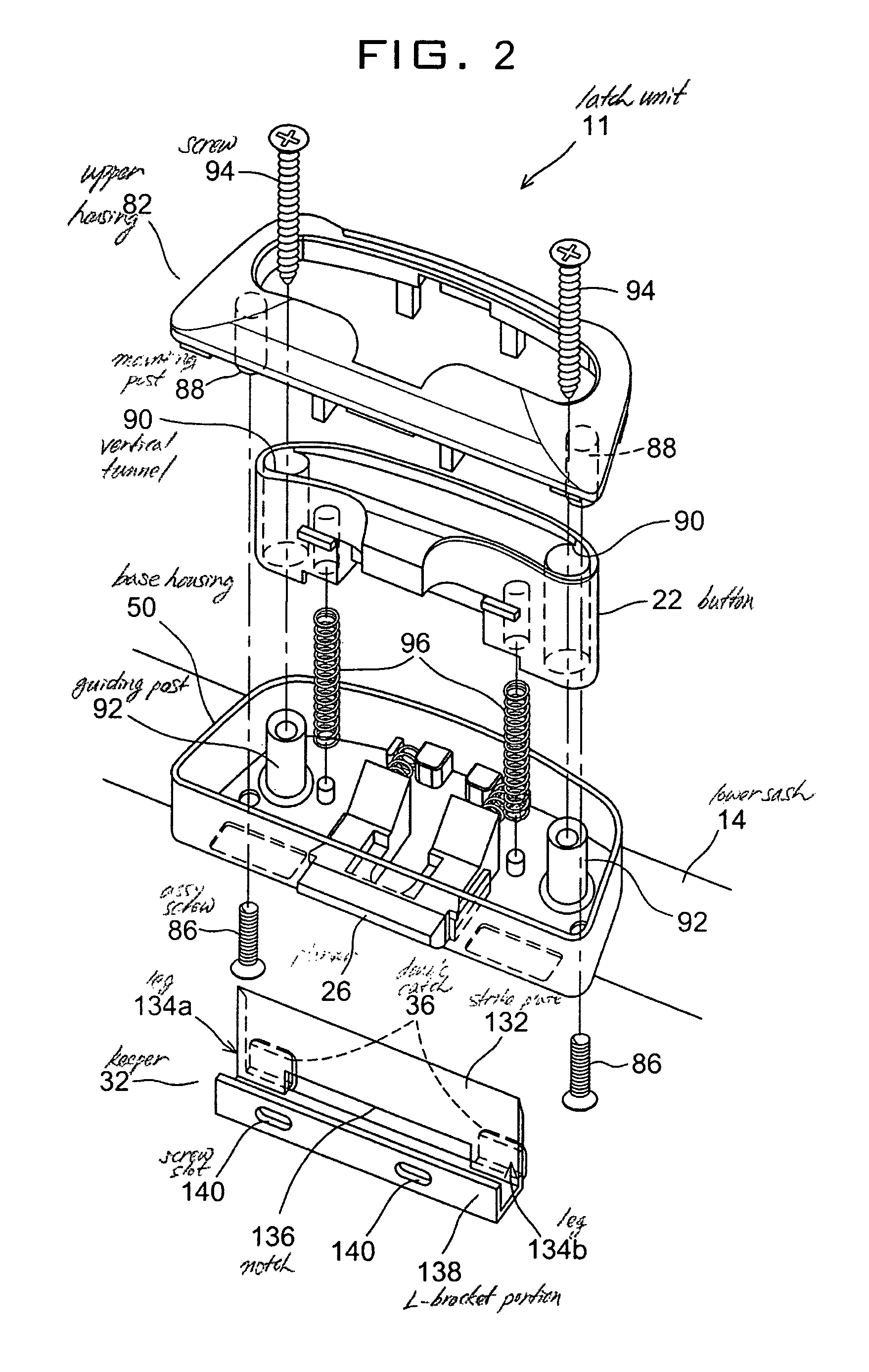
[0085]With reference to FIG. 1, a window lock assembly 10 of the present invention generally comprises a latch unit 11 and a keeper 32 and is made for a sliding window 12 that may includes a rectangular inner lower sash 14 shown at its top cross sectional area and a similarly shaped outer upper sash 16 shown at its bottom cross sectional area for mating with the lower sash 14 to close window 12 as the lower sash 14 slides over the upper sash 16 in a window frame (not shown). Lower sash 14 encases downwardly extending glass panes 18 and a sealing 20 between the panes 18. In the window 12 illustrated, latch unit 11 may be mounted on the top middle surface of lower sash 14.

[0086]Besides covering the interior room of a building from the elements, window 12 may obtain an improved security and aesthetic value from the sash lock 10 that may be installed initially at the time of building a house or home improvements wherein the owner may replace the old bulky locking devices with this mecha...


PUM


Abstract

A sash lock for use with door and window is provided. The lock has a base housing shaped into a laterally extending crib to contain a partially protruding plunger sliding under a forward bias, a large button block that occupies a substantial area at the top of the lock to allow for a unique squeeze release of the plunger and translates in a perpendicular plane with respect to the plunger movement under an expansive bias for normally pushing the button block away from the base housing in cooperation with the biased counteraction of the cam surfaces of the plunger but yielding to a manual depression to activate the plunger through a cam engagement, and a top housing fastened to the base housing to enclose the plunger and button block. The plunger has cam surfaces at a rear end facing forwardly and a beveled lip portion at a front end while the button block has a beveled surface facing the cam surfaces of the plunger. The sash lock further comprises two identical holes formed in the bottom of base housing and a separate keeper for interlocking with the base housing.

Description

BACKGROUND OF THE INVENTION[0001]A. Field of the Invention[0002]The present invention relates to door and window hardware. More particularly, the present invention relates to a mechanically stable and ergonomically improved door and window sash lock.[0003]B. Description of the Prior Art[0004]Sliding windows or patio doors in a building are made for letting in necessary light and air into the room while allowing occupants to have a comfortable viewing of the surrounding nature. At the same time, such doors or windows should be able to lock out harmful elements and potential intruders.[0005]Window latches and locks that are also applied to doors have been developed as the windows in the modernized buildings have long been evolved all together. Of different types of slider window, a single-hung type window is structured to have an upper outside pane in a stationary sash and an inside pane in a sliding sash guided in a window frame along its vertical path between a raised level position...

Claims


Application Information

Patent Timeline
Patent Type & Authority Patents(United States)
IPC IPC(8): E05C1/08
CPCE05B65/0864E05C2007/007Y10S292/20Y10S292/47Y10T292/1041Y10T292/0969Y10T292/0976
Inventor YE, JINTIAN
Owner YE JINTIAN
Why Eureka
Try Eureka