
Disc changer having disc discharge mechanism

a technology of disc changer and discharge mechanism, which is applied in the field of disc changer, can solve problems such as disc collision, and achieve the effect of smooth discharg

Inactive Publication Date: 2010-06-01
FUJITSU GENERAL LTD
View PDF22 Cites 2 Cited by
  • Summary
  • Abstract
  • Description
  • Claims
  • Application Information

AI Technical Summary

Benefits of technology

The present invention provides a disc changer for a disc drive unit that has a disc guiding device to solve the problem of disc discharge from the disc drive unit. The guiding member is positioned near the disc discharge opening and guides the disc to the disc discharge mechanism. The guiding member is evacuated at the time of reproducing the content of the disc to avoid interference with the disc. The guiding member is driven at the time of disc discharge to form a tapered surface from the carrying mechanism side towards the disc discharge opening. The guiding member can be fixed or only the lower part moved. The drive mechanism of the guiding member is the same as the drive mechanism of the carrying mechanism. The guiding member increases its slope angle when the rotation angle of the carrying mechanism becomes larger. The disc exchanger of the present invention allows for smooth discharge of discs from the disc drive unit without collisions.

Problems solved by technology

This has a risk that the disc is collided against the disc insertion / discharge opening of the disc drive unit, when the pushing mechanism pushes the disc to the position where the disc is to be discharged by a roller and when the roller discharges the disc from the disc insertion / discharge opening.

Method used


Image

  • Disc changer having disc discharge mechanism
  • Disc changer having disc discharge mechanism
  • Disc changer having disc discharge mechanism

Examples


Embodiment Construction

[0033]Disc changers according to embodiments of the present invention are explained in detail below with reference to the accompanying drawings.

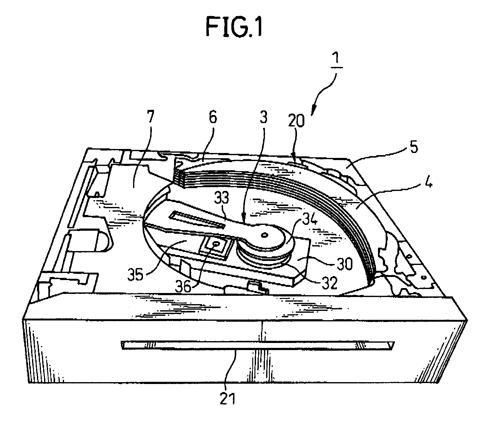
[0034]FIG. 1 is a perspective view of a configuration of a disc changer 1 to which the present invention is applied, where a disc is not accommodated. The disc changer 1 to which the present invention is applied includes a stocker 4 as a disc accommodation section capable of accommodating plural discs and capable of being lifted up and moved down within the disc changer, a swing arm 3 that takes out a disc from the stocker 4, reproduces content of the disc, and returns the disc to the stocker 4 after the reproduction, a drive unit 7 of the swing arm 3, a linear position sensor (not shown) that detects a position of the stocker 4, and a lifting mechanism 5 that lifts up and moves down the stocker 4 based on an output of the linear position sensor.

[0035]The swing arm 3 is rotated by the drive unit 7, and broadly includes a frame 30 and a clamp...


PUM

PropertyMeasurementUnit
discharge timeaaaaaaaaaa
movementaaaaaaaaaa
slope angleaaaaaaaaaa

Abstract

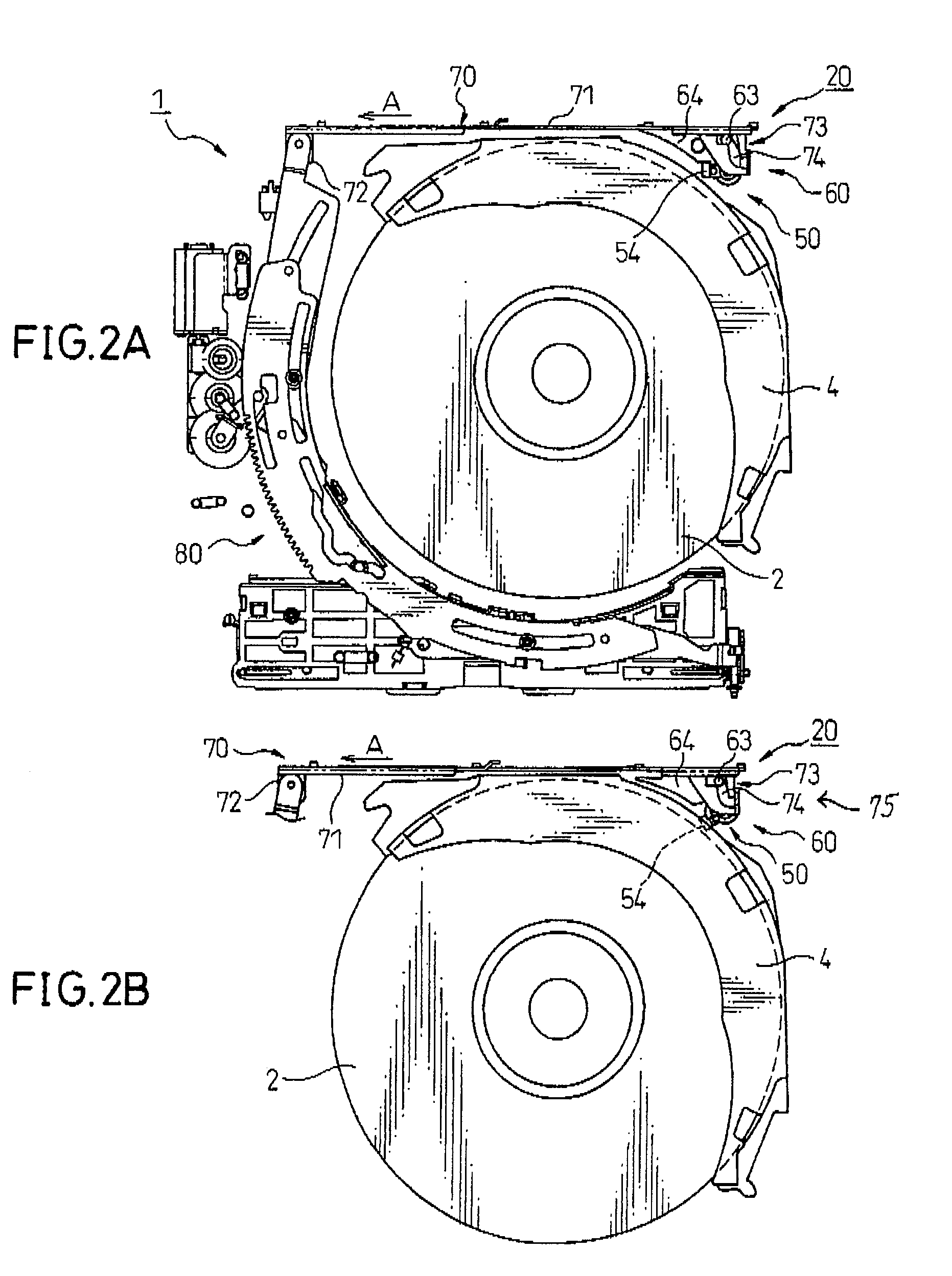
There is provided a disc changer for a disc drive unit, including: a disc accommodation section capable of accommodating plural discs: a disc pushing mechanism that pushes a disc from a specific rack of the disc accommodation section to a disc discharge position within the disc drive unit; and a disc discharge mechanism that securely sends the disc at the disc discharge position, to a disc insertion / discharge opening of the disc drive unit. The disc exchanger further includes a disc guiding device that has: an upper and a lower guiding members, which are provided in an area within the disc drive unit adjacent to the disc insertion / discharge opening, and guide the disc pushed by the pushing mechanism, to the disc insertion / discharge opening; and a drive mechanism of the guiding members, that opens the lower guiding member from the upper guiding member, when the pushing mechanism pushes the disc.

Description

CROSS-REFERENCE TO RELATED APPLICATION[0001]This application claims priority from, and incorporates by reference the entire disclosure of, Japanese Patent Application No. 2005-015158, filed on Jan. 24, 2005, and Japanese Patent Application No. 2005-379233, filed on Dec. 28, 2005.BACKGROUND OF THE INVENTION[0002]1. Field of the Invention[0003]The present invention relates to a disc changer. Particularly, the invention relates to a disc changer incorporated in a disc drive unit, the disc changer having a disc guiding device structured to expand an opening of a disc discharging guide, provided inside the disc drive unit near a disc insertion / discharge opening, at the time of discharging a disc to the outside of the disc drive unit.[0004]2. Description of the Related Art[0005]Conventionally, a cassette tape has been the mainstream medium recorded with music to provide music in a motor vehicle, However, a disc medium such as a compact disc (CD) and a mini disc (MD) is now mainly used in ...

Claims


Application Information

Patent Timeline
Patent Type & Authority Patents(United States)
IPC IPC(8): G11B17/03G11B17/04G11B33/02
CPCG11B17/021G11B17/223G11B17/051
Inventor GOTO, TSUTOMU
Owner FUJITSU GENERAL LTD
Learn More