
Camera glare reduction system and method

a technology of glare reduction and camera, applied in the field of selective light transmitting and receiving systems and methods, can solve the problems of affecting the clarity of taken images, glare directly from the sun or by way of reflective objects, and the use of polarized filters does not protect well against glare emanating from most man-made light sources, so as to reduce unwanted glare and/or other light emission

Inactive Publication Date: 2010-06-01
TECH4ALL
View PDF40 Cites 25 Cited by
  • Summary
  • Abstract
  • Description
  • Claims
  • Application Information

AI Technical Summary

Benefits of technology

"The patent describes a camera system that reduces unwanted glare and other light emission by using a polarized filter to block reflected light. The system also allows users to selectively position the polarized filter for improved glare reduction. Additionally, the patent describes a method for generating a resultant image by setting an active polarizing filter to different polarization angles and recording two images, which is then blended to form the resultant image. The technical effects of this invention include improved image quality and reduced glare."

Problems solved by technology

Further, with recent technological advances in cameras, along with accompanying price drops, even the most mundane activities and events are now recorded.
An early problem encountered in photography was glare directly from the Sun or by way of reflective objects.
In some cases, this glare may be undesirable and can adversely affect the clarity of the taken images.
However, the use of polarized filters does not protect well against glare emanating from most man-made light sources, such as camera light sources including flash sources and spot light sources.
Accordingly, camera polarized filters cannot effectively reduce glare caused by most man-made light sources.
Thus, the image taken is susceptible to impaired image quality due to glare emanating from camera light sources.

Method used


Image

  • Camera glare reduction system and method
  • Camera glare reduction system and method
  • Camera glare reduction system and method

Examples


Embodiment Construction

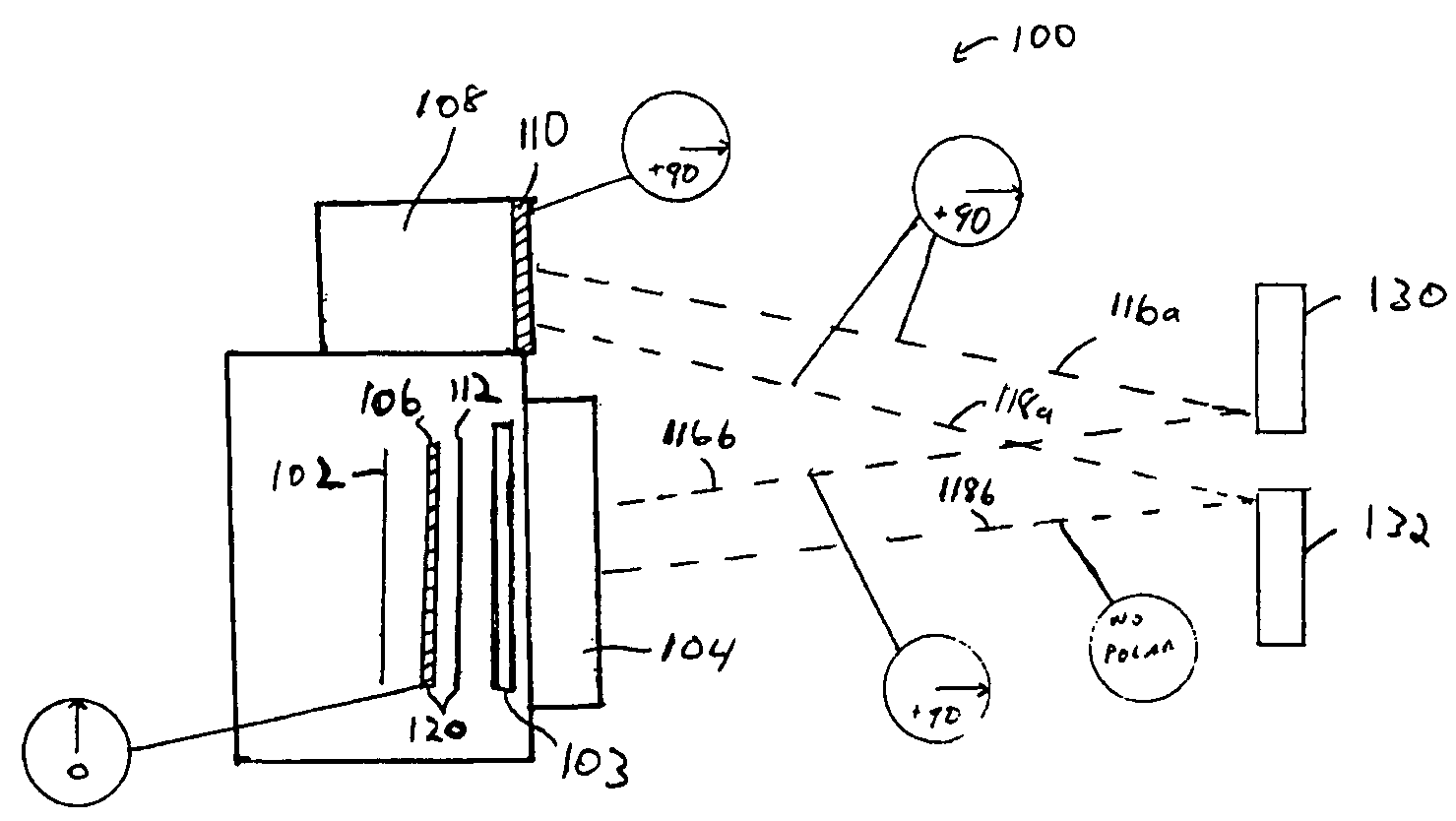
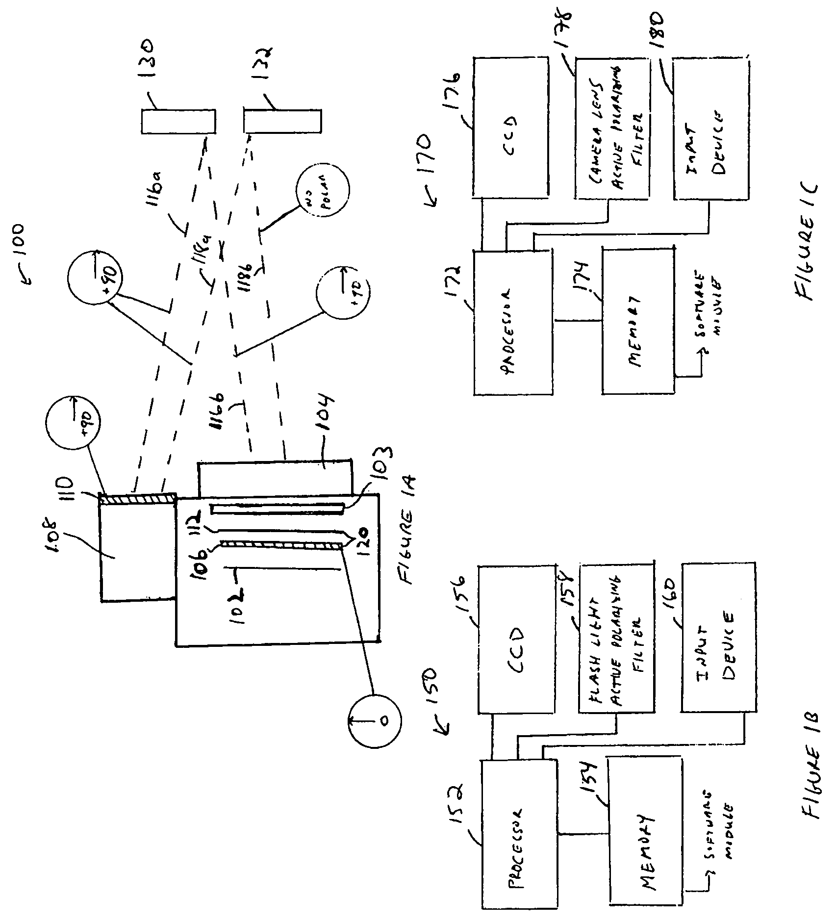
[0026]FIG. 1A illustrates a side view of an exemplary camera glare reduction system 100 in accordance with an embodiment of the invention. The camera glare reduction system 100 comprises an image-capturing device 102 (e.g., a film or a charged coupled device (CCD)), a shutter 103, a lens 104, a flash light source 108, a first polarized filter 110, and an active polarized filter 120. The active polarized filter 120 comprises a liquid crystal layer (LCL) 112 and a second polarized filter 106. The first polarized filter 110 polarizes the light emanating from the flash light source 108 in a substantially horizontal orientation (e.g., +90 degrees). The second polarized filter 106 has a substantially vertical (e.g., zero (0) degree) polarization. In combination with the second polarized filter 106, the LCL 112 selectively adjusts the effective polarization θ of the active polarized filter 120 by rotating the polarization of the incident light. In an exemplary embodiment, the effective pol...


PUM


Abstract

Various image-capturing systems are disclosed that use polarized filters to reduce or control glare effects on captured images. In one embodiment, the system includes a light source, a first polarized filter adapted to polarize light emanating from the light source; a second polarized filter adapted to perform polarized filtering on received light; and an image-capturing device adapted to receive the filtered light. In another embodiment, the system further includes an actuator to selectively move any of the polarized filter into and out of the light path. In yet another embodiment, a method of forming a resultant image comprises recording a first image with a filter set to a first polarization angle, recording a second image with the filter set to a second polarization angle, and blending the first and second images. The recording of the first and second images may be performed simultaneously or at different times.

Description

FIELD OF THE INVENTION[0001]This invention relates generally to selective light transmitting and receiving systems and methods, and in particular, to a selective light transmitting and receiving system and method that use polarized filters to remove unwanted camera glare and / or other light emissions.BACKGROUND OF THE INVENTION[0002]Photography is an immensely popular activity. The works of professional still-picture photographers are illustrated everyday in newspapers, magazines, and advertisements, and the works of professional moving-picture photographers are present in television and films. Countless amateur photographers take pictures to capture many life's events. Further, with recent technological advances in cameras, along with accompanying price drops, even the most mundane activities and events are now recorded.[0003]An early problem encountered in photography was glare directly from the Sun or by way of reflective objects. A small portion of sunlight is polarized when it p...

Claims


Application Information

Patent Timeline
Patent Type & Authority Patents(United States)
IPC IPC(8): G03B15/03G03B7/099H04N5/225
CPCG03B15/03G03B11/00
Inventor KARIM, JOHN H.
Owner TECH4ALL
Learn More