
LED lamp

a technology of led lamps and led lamps, applied in the field of led lamps, can solve the problems of increasing the price and power consumption of modules, and being unsuitable for environments requiring even and broad illumination

Inactive Publication Date: 2010-06-01
FU ZHUN PRECISION IND SHENZHEN +1
View PDF3 Cites 28 Cited by
  • Summary
  • Abstract
  • Description
  • Claims
  • Application Information

AI Technical Summary

Benefits of technology

[0004]An LED lamp utilizes light-emitting diodes (LEDs) as a source of illumination, in which current flowing in one direction through a junction region comprising two different semiconductors results in electrons and holes coupling at the junction region and generating a light beam. The LED is resistant to shock and has a nearly infinite lifetime under specific conditions, making it a popular cost-effective and high quality replacement for incandescent and fluorescent lamps.

Problems solved by technology

The large number of LEDs, however, increases price and power consumption of the module.
Considerable heat is also generated, which, if not adequately addressed at additional expense, impacts LED lamp reliability.
Further, since the LEDs are generally arranged on a printed circuit board having a planar surface, illumination is distributed at a wide variety of spatial angles with marked differences in intensity and brightness, making it unsuitable for environments requiring even and broad illumination.

Method used


Image

  • LED lamp
  • LED lamp
  • LED lamp

Examples


Embodiment Construction

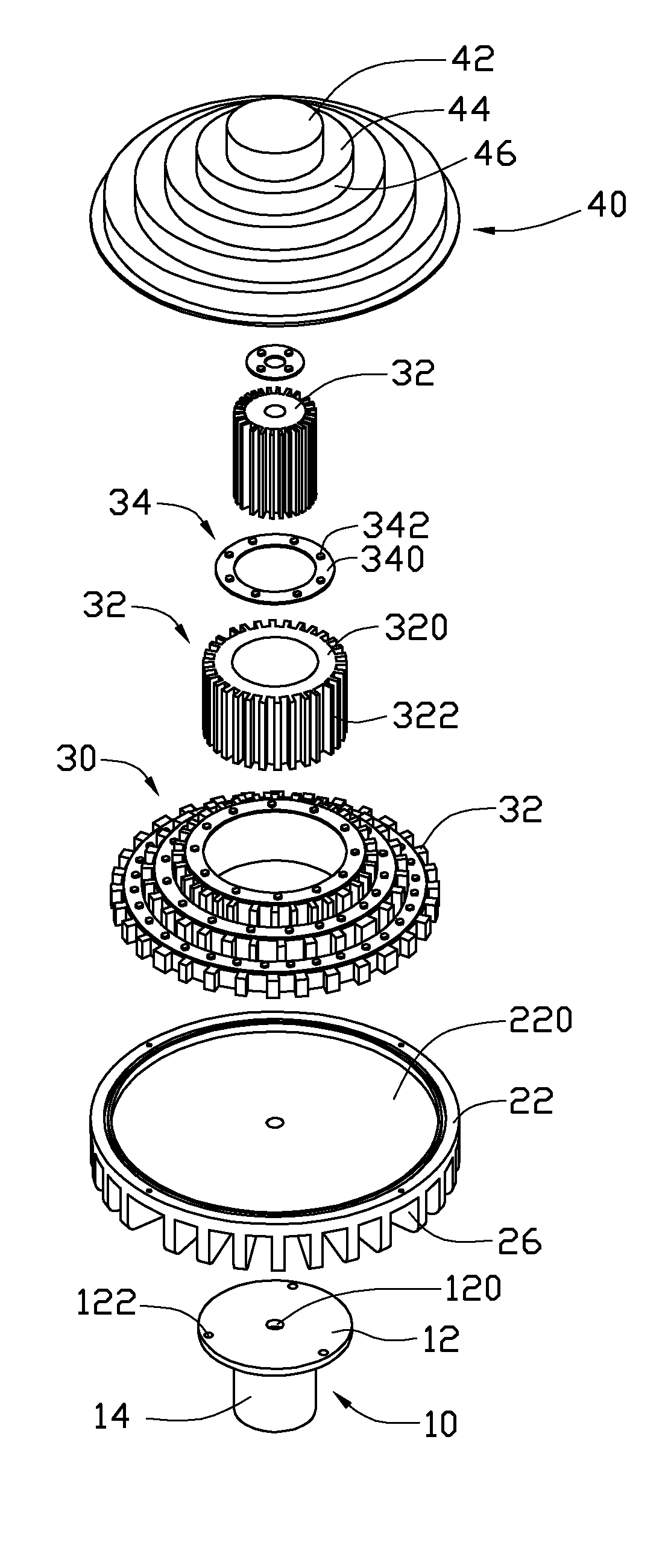
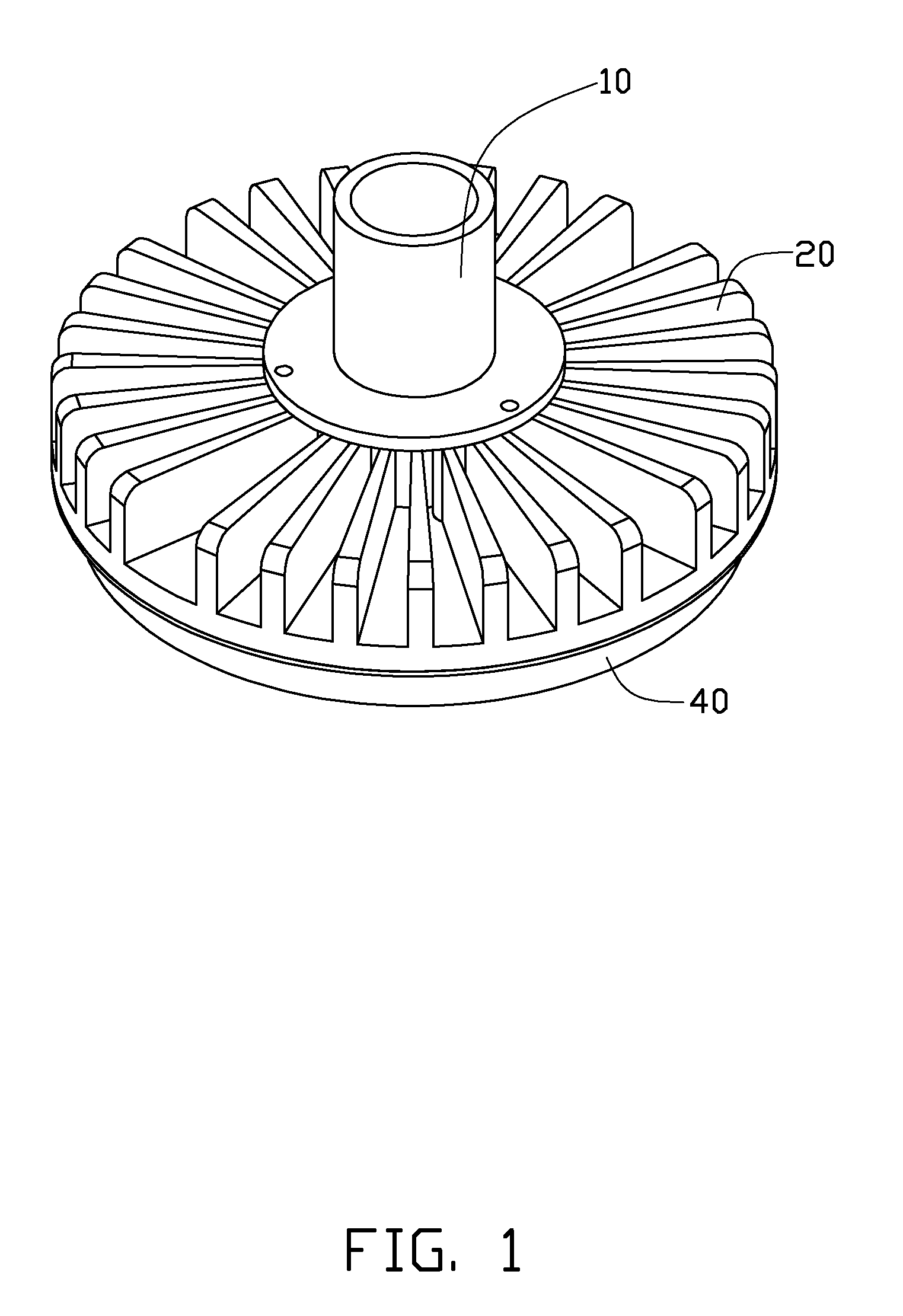
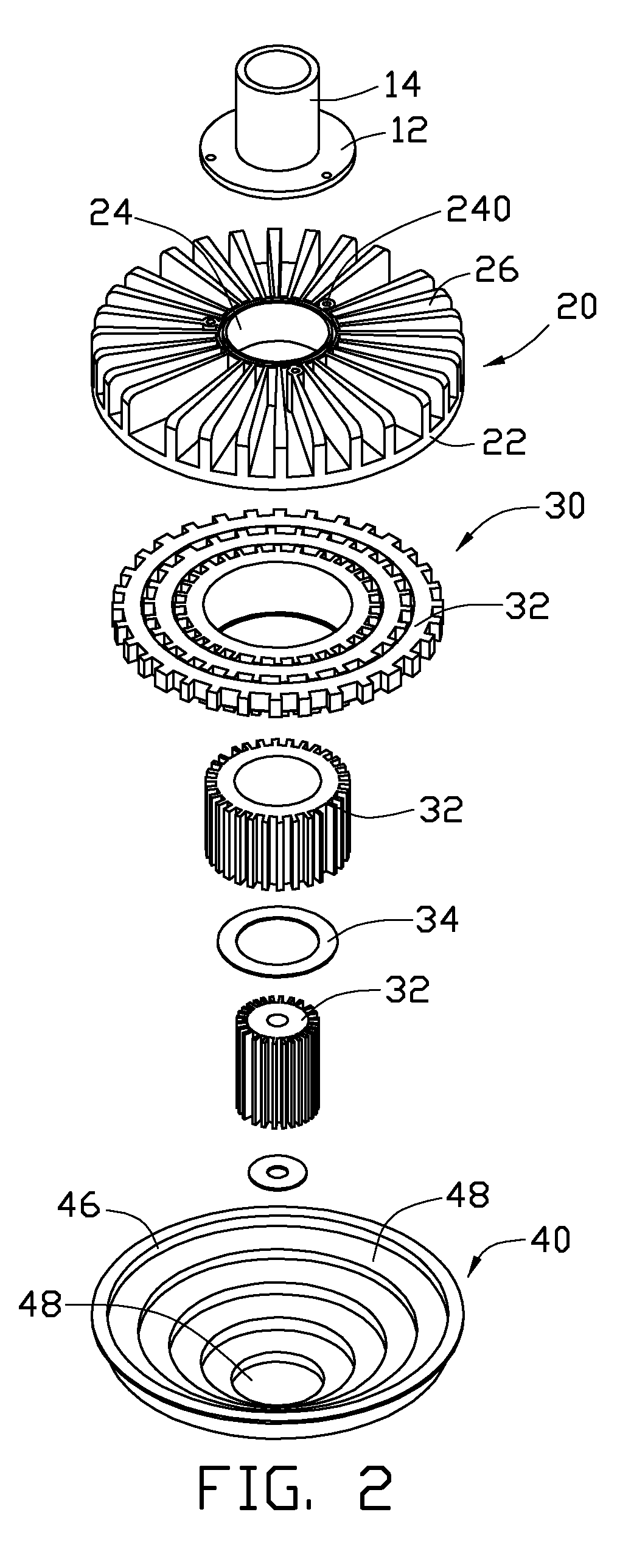
[0013]Referring to FIGS. 1-4, an LED lamp in accordance with a preferred embodiment is illustrated. The LED lamp, which is configured for providing illumination indoors and outdoors, includes a fixing rod 10, a first heat sink 20 fixing to the fixing rod 10, a second heat sink 30 fixed to a bottom of the first heat sink 20, a plurality of LED modules 34 attached to the second heat sink 30 and a lamp cover 40 engaging the first heat sink 20 to enclose the second heat sink 30 and the LED modules 34.

[0014]The fixing rod 10 is used for connecting with a mounting post (now shown) to thereby position the LED lamp at a desired position, and comprises a circular mounting plate 12 and a hollow tube 14 extending upwardly and perpendicularly from a top surface of a center of the mounting plate 12. The mounting plate 12 defines a through hole 120 in the center thereof and three mounting holes 122 therein. The three mounting holes 122 are located symmetrically relative to the through hole 120 al...


PUM

PropertyMeasurementUnit
heat-conductingaaaaaaaaaa
heat-conducting aaaaaaaaaa
circumferenceaaaaaaaaaa

Abstract

An LED lamp includes a fixing rod, a first heat sink mounted to the fixing rod, a second heat sink mounted on the first heat sink, a plurality of LED modules attached on the second heat sink and a lamp cover engaging the first heat sink to enclose the second heat sink and the LED modules. The second heat sink includes a plurality of heat-conducting faces formed on a bottom end thereof and arranged at different levels. The LED modules are respectively attached on the heat-conducting faces of the second heat sink. The lamp cover includes a panel and a plurality of annular steps extending outwardly from the panel in sequence. Each annular step has a concave lens attached thereon. The annular steps are located corresponding to the LED modules of the second heat sink, respectively.

Description

BACKGROUND OF THE INVENTION[0001]1. Field of the Invention[0002]The disclosure relates to an LED lamp, and more particularly to an LED lamp having a wide illumination area.[0003]2. Description of Related Art[0004]An LED lamp utilizes light-emitting diodes (LEDs) as a source of illumination, in which current flowing in one direction through a junction region comprising two different semiconductors results in electrons and holes coupling at the junction region and generating a light beam. The LED is resistant to shock and has a nearly infinite lifetime under specific conditions, making it a popular cost-effective and high quality replacement for incandescent and fluorescent lamps.[0005]Known implementations of LED modules in an LED lamp make use of a plurality of individual LEDs to generate light. The large number of LEDs, however, increases price and power consumption of the module. Considerable heat is also generated, which, if not adequately addressed at additional expense, impacts...

Claims


Application Information

Patent Timeline
Patent Type & Authority Patents(United States)
IPC IPC(8): F21V29/00
CPCF21V5/04F21V29/004F21V29/773F21V29/713F21K9/00F21V21/116H01L2924/0002F21Y2101/02H01L2924/00F21V29/89F21Y2115/10F21K9/20F21K9/69F21V3/062F21V3/061F21V29/777
Inventor YANG, RI-LANGYU, GUANG
Owner FU ZHUN PRECISION IND SHENZHEN
Learn More