
Wall hook

a wall hook and hook technology, applied in the field of wall hooks, can solve the problems of reducing the hanging ability of the wall hooker, reducing the overall structural configuration, and user applying a relatively large rotational force, so as to reduce the torque distance and minimize the torque

Inactive Publication Date: 2010-06-01
LIEN CHIN HSIUNG
View PDF6 Cites 19 Cited by
  • Summary
  • Abstract
  • Description
  • Claims
  • Application Information

AI Technical Summary

Benefits of technology

[0008]A main object of the present invention is to provide a wall hook, wherein the wall hook is adapted for increasing the torque distance so as to minimize a torque required to directly apply at the inserting head.
[0009]Another object of the present invention is to provide a wall hook, wherein the wall hook comprises a levering handle extending from the inserting head to prolong the torque such that the user is able to penetrate the inserting head by rotating the levering handle with respect to the rotational axis so as to minimize the deformation of the mounting hole.
[0010]Another object of the present invention is to provide a wall hook, wherein the user is able to easily mount the wall hook to the wall by less rotational force in a tool-less manner. In other words, the user can use his or her hand to mount the wall hook without any screw driver or the like.

Problems solved by technology

However, such wall hanger has a major drawback that the user must apply a relatively large rotational force at the hanging hook in order to force the pin head to penetrate through the wall surface.
Since the wall hanger is used as a hanging device to hang the item on the wall, the deformation of the mounting hole will weaken the retention force along the pin head so as to reduce the hanging ability of the wall hanger.
However, the improved wall hanger requires a tool, such as a screw driver, to install the wall base on the wall and involves different components, i.e. the wall base, the hanger body, and the screw, which will complicate the overall structural configuration and will significantly increase the manufacturing cost of the wall hanger.
Thus, the size of the improved wall hanger is relatively larger than the conventional one-piece wall hanger such that the user will not use the improved wall hanger for hanging the picture frame on the wall.
In addition, the clip hook having a C shape cannot securely hold the cable in position.
It is a hassle for the user to place the cable within the clip hook if the size of the opening of the clip hook is reduced to prevent the cable accidentally detaching therefrom.
As a result, no matter which type of the wall hook is used, the wall surface will be damaged by the deformation of the mounting hole.
It is worth to mention that when the wall hook is used for supporting a relatively heavy item, the deformation of the mounting hole will be getting more serious.

Method used


Image

  • Wall hook
  • Wall hook
  • Wall hook

Examples


Embodiment Construction

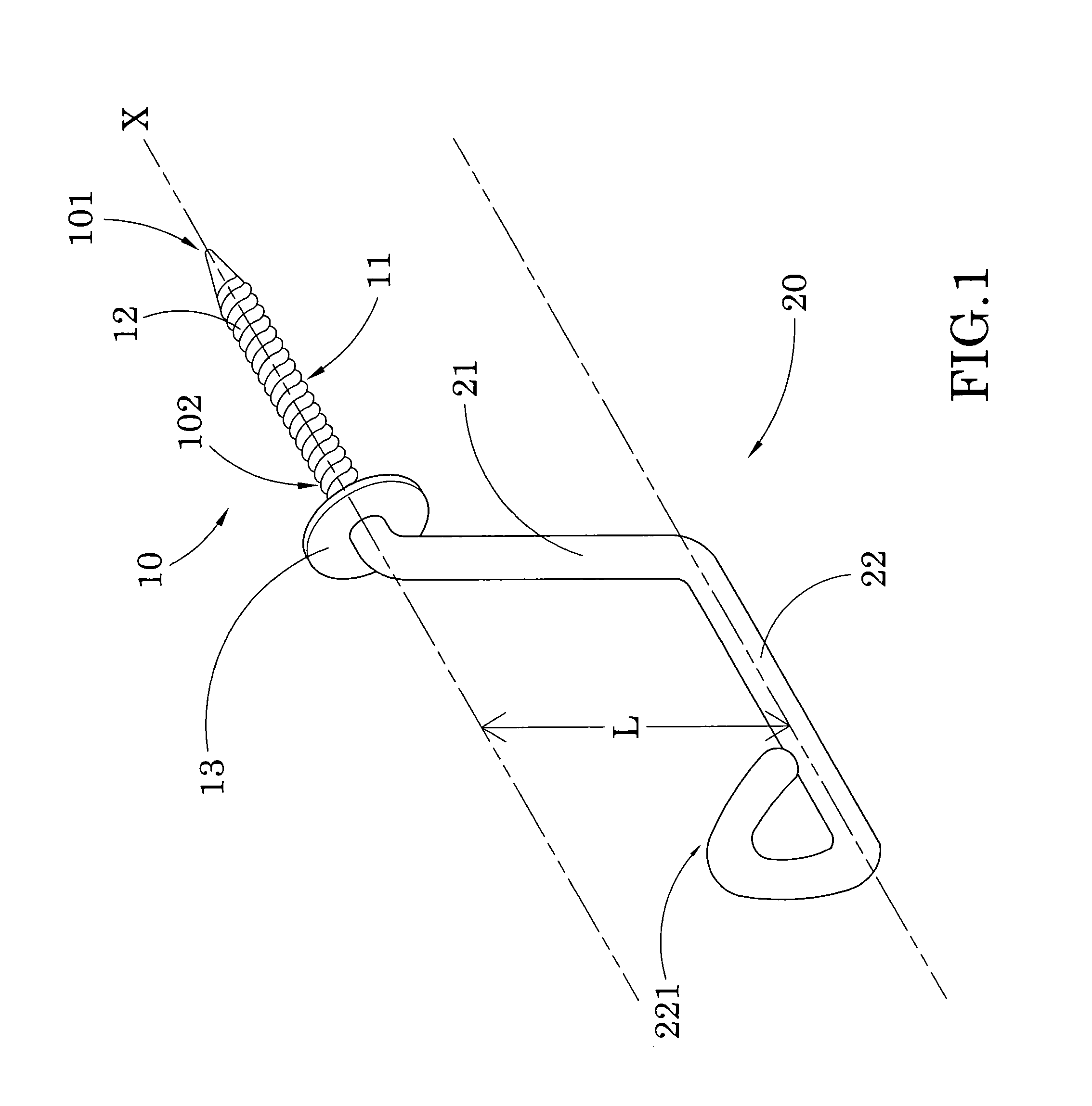
[0023]Referring to FIG. 1 of the drawing, a wall hook for mounting on a wall W or the like according to a first preferred embodiment of the present invention is illustrated, wherein the wall hook, which is adapted for mounting on a wall W, especially for a dry wall, comprises an inserting head 10 and a levering handle 20.

[0024]As shown in FIGS. 1 and 2, the inserting head 10, which defines a rotational axis X, has a front penetrating tip 101 adapted for rotatably inserting into a wall surface of the wall W and a rear fulcrum end 102 rearwardly extended from the penetrating tip 101 along the rotational axis X. Accordingly, in order to perpendicularly insert the inserting head 10 into the wall surface of the wall W, the inserting head 10 must be driven to rotate with respect to the rotational axis X to form a mounting hole on the wall W.

[0025]The inserting head 10 comprises an elongated inserting body 11 having a predetermined length for inserting into the wall W, and has a spiral thr...


PUM


Abstract

A wall hook includes an inserting head defining a rotational axis, and a levering handle. The inserting head has a front penetrating tip adapted for rotatably inserting into a wall surface of the wall and a rear fulcrum end rearwardly extended from the penetrating tip along the rotational axis. The levering handle has a transverse arm integrally and transversely extended from the fulcrum end of the inserting head to substantially prolong a torque distance along the transverse arm with respect to the rotational axis, and a controlling arm integrally extended from the transverse arm in such a manner that when the levering handle is rotated, the inserting head is driven to rotate for rotatably penetrating into the wall so as to minimize a torque required to directly apply at the inserting head.

Description

BACKGROUND OF THE PRESENT INVENTION[0001]1. Field of Invention[0002]The present invention relates to a wall hook, and more particularly to a wall hook, wherein the wall hook comprises an inserting head and a transverse arm transversely extending therefrom for increasing the torque distance to minimize a torque required to directly apply at the inserting head.[0003]2. Description of Related Arts[0004]A wall hook is considered as one of the common wall accessories to hold an item on the wall. Generally speaking, there are two types of wall hook in the existing market. The first type of wall hook is a wall hanger adapted for mounting on a flat wall surface to hang the item, such as cloth or picture frame, on the wall. Accordingly, such wall hanger, which is a one-piece hanging device, generally comprises a pin head having a screwing axis and a hanging hook rearwardly extended from the pine head along the screwing axis, such that when the user drives the hanging hook to rotate with resp...

Claims


Application Information

Patent Timeline
Patent Type & Authority Patents(United States)
IPC IPC(8): A47H1/16
CPCA47G1/20F16B45/00F16B35/06A47G2001/207
Inventor LIEN, CHIN-HSIUNG
Owner LIEN CHIN HSIUNG
Learn More