
Container closure and closure lid for said container closure

a container and closure technology, applied in the direction of closures, closures, engine cooling devices, etc., can solve the problem of sudden jumping of the closure lid

Inactive Publication Date: 2010-06-01
REUTTER HEINRICH
View PDF17 Cites 6 Cited by
  • Summary
  • Abstract
  • Description
  • Claims
  • Application Information

AI Technical Summary

Benefits of technology

"The present invention relates to a closure lid for a container and a container closure, which are designed to prevent the champagne cork effect caused by the sealing ring lifting radially away from the groove bottom. The invention achieves this by providing an annular rib with an uneven contact face for the sealing ring in the closure lid or the container closure. This allows for an advance venting route and prevents the sealing ring from lifting radially outward from the bottom of the annular groove, thus avoiding the champagne cork effect. The invention also includes support ribs that protrude into the annular groove and are distributed over the circumference, which provide a linear support of the sealing ring and allow for an adequate axial motion of the sealing ring during overpressure in the container interior. Additionally, the invention includes recesses or indentations in the annular rib contact face or faces, which provide encompassing groove the axial mobility or predformed fixation of the sealing ring. Overall, the invention ensures a total pressure equalization and prevents the champagne cork effect at a relatively high overpressure in the container interior."

Problems solved by technology

Although this does substantially prevent the aforementioned champagne cork effect, nevertheless, because the overpressure is only partly reduced, a residual pressure in the container remains, which especially upon very fast release or unscrewing of the closure lid can still cause the closure lid to jump off suddenly, even if only slightly.

Method used


Image

  • Container closure and closure lid for said container closure
  • Container closure and closure lid for said container closure
  • Container closure and closure lid for said container closure

Examples


Embodiment Construction

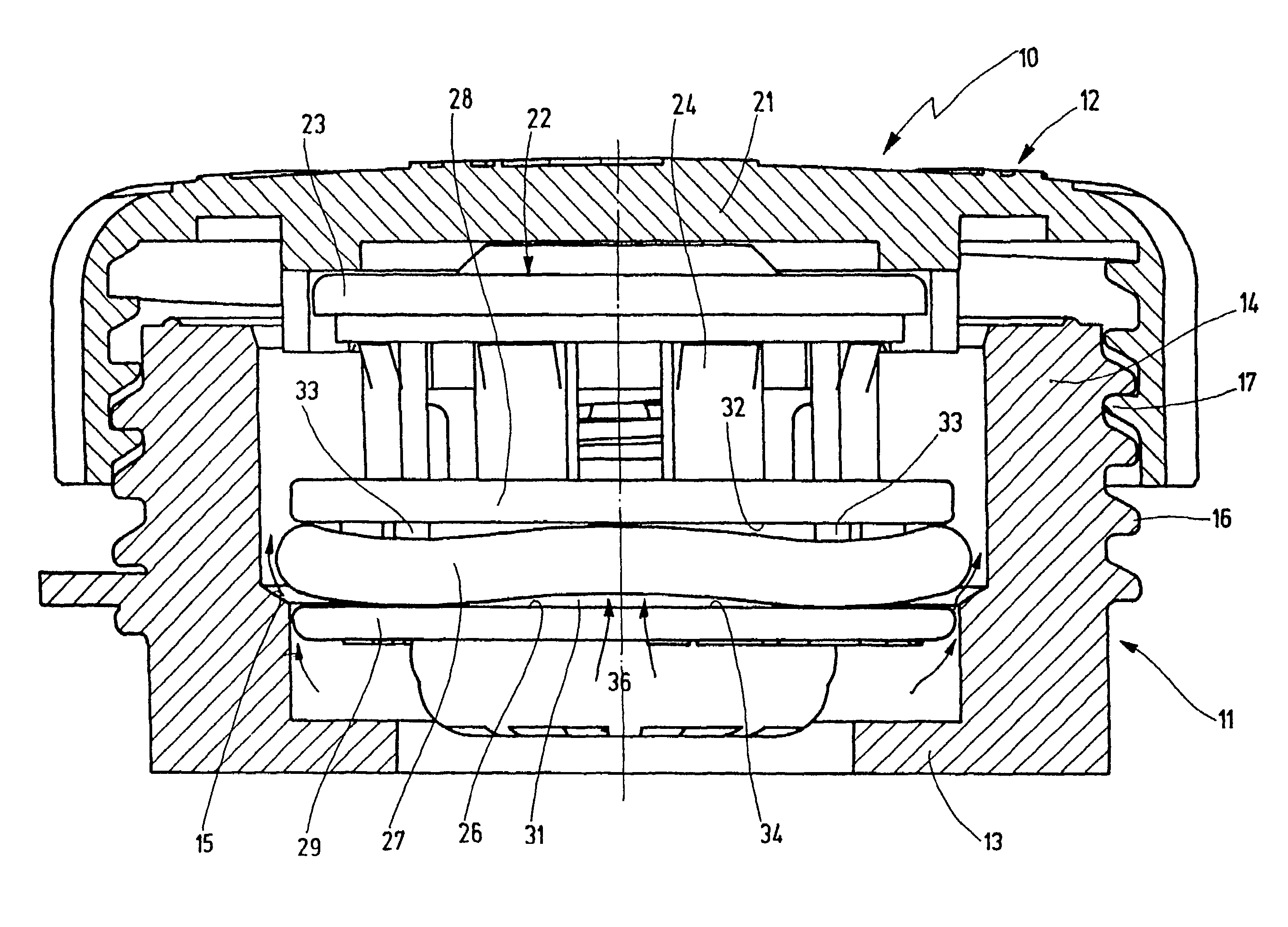
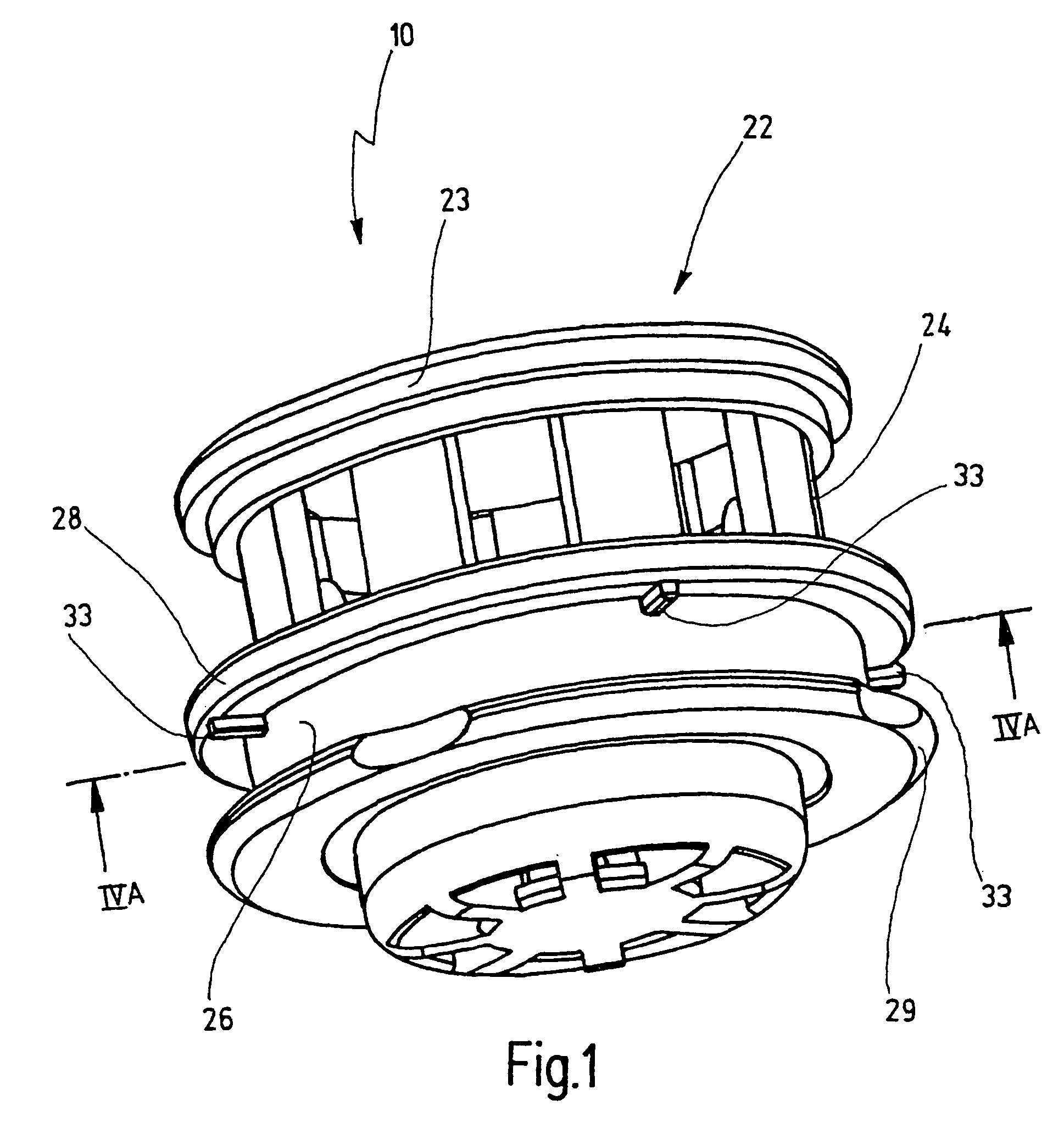
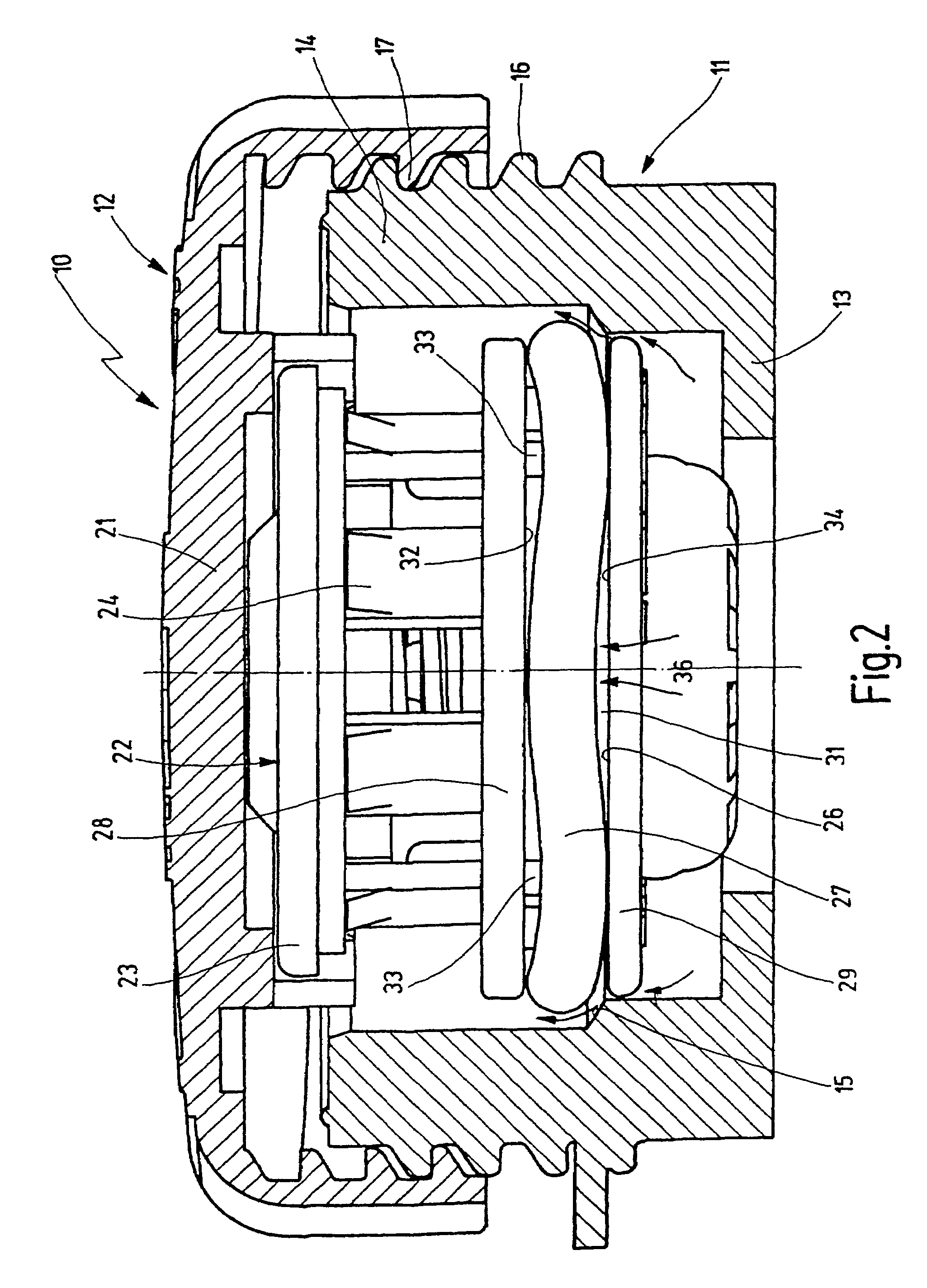
[0018]FIGS. 1 and 2, and the one hand, and FIG. 3 on the other, show two embodiments, each with a container closure 10 embodied essentially rotationally symmetrically, which has a container neck 11 and a closure lid 12 or 12′ screwed onto the container neck.

[0019]The container neck 11 on the bottom has a narrowed neck portion 13, which is in communication with an opening in a container, not shown, preferably a radiator for internal combustion engines. An enlarged neck portion 14 is provided in the upper region of the container neck 11 and is joined to the lower neck portion 13 via a conical intermediate portion (ramp) 15. The container neck 11 is provided with a male thread 16, by way of which the closure lid 12, 12′ can be screwed to a female thread 17, or in other words can be screwed on and unscrewed.

[0020]The closure lid 12 and 12′ has a caplike outer part 21, which fits over the container neck 11 and which is provided with the female thread 17 for screwing onto and unscrewing f...


PUM


Abstract

A closure lid for a connecting element of a computer container, comprising an inner part which is maintained on an outer part of said lid and which is provided with an annular groove on the outer periphery thereof, said groove being defined by an annular web on the outer side of the lid and having a sealing ring inserted therein. In order to provide a closure lid which is embodied in such a way that it is possible to prevent the sealing ring from being raised radially from the base of the groove as a result of existing pressure and therefore to relieve the pressure inside the container before the open position of the closure container is reached, the annular web disposed on the outer side of the lid is provided with an uneven bearing surface for the sealing ring.

Description

FIELD OF THE INVENTION[0001]The present invention relates to a closure lid for the container neck of a container closure having an inner part that is retained on an outer part provided on its outer circumference with an annular groove defined by an annular rib toward the outer part, and into which a sealing ring is inserted; and a container closure having such a closure lid which is movable between an open position, in which it can be removed from the container neck and a closing position in which it is moved axially with its inner part into the container neck, and the inner part is provided on the outside with an annular groove defined by an annular rib toward the lid and into which a sealing ring is inserted. The container neck at the level of the sealing ring, when the closure lid is in the closing position, has a sealing face on which the sealing ring rests sealingly, and when the closure lid is in a position between the closing and open positions, has a radial neck enlargement ...

Claims


Application Information

Patent Timeline
Patent Type & Authority Patents(United States)
IPC IPC(8): B65D53/02B65D51/16F01P11/02
CPCB65D51/16F01P11/0209F01P2011/0228
Inventor REUTTER, HEINRICH
Owner REUTTER HEINRICH
Learn More