Eureka AIR delivers breakthrough ideas for toughest innovation challenges, trusted by R&D personnel around the world.

Method for manufacturing a felt belt, and felt belt

a manufacturing method and felt belt technology, applied in the field of felt belt manufacturing, can solve the problems of limited usability of paper machine felt belts, limited suitability of supports for press felt manufacture, and low transverse strength of felt belts, and achieves simple and therefore economical fashion and high transverse strength

Active Publication Date: 2010-05-25
HEIMBACH GMBH & CO KG
View PDF16 Cites 16 Cited by
  • Summary
  • Abstract
  • Description
  • Claims
  • Application Information

AI Technical Summary

Benefits of technology

[0012]It is the object of the invention to make available a method for manufacturing a felt belt having a support, which latter is constructed from longitudinal and transverse yarn layers and embedded into a fiber matrix, with which a felt belt can be manufactured in simple and therefore economical fashion and with high transverse strength and properties that are consistent over its width.
[0026]With the aid of this method, felt belts can be manufactured in simple and economical fashion utilizing the advantages of a winding process. Because they comprise continuous transverse yarns, their transverse strength is high. The felt belts are furthermore notable for the fact that their properties, in particular their permeability to water, which is important for use in a paper machine, are uniform over their surface.
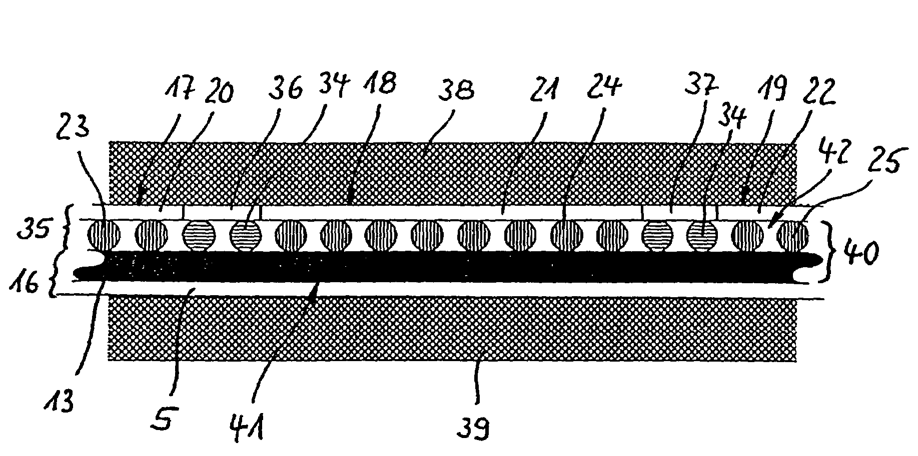
[0039]The subject matter of the invention is furthermore a felt belt that has been manufactured with the aid of the method according to the present invention and accordingly comprises a support that is embedded in a fiber matrix and is made up of at least two yarn layers arranged one above another, transverse yarns being present that are continuous over the width of the felt belt, and the yarns having the property of absorbing laser energy so that they can be brought by means of laser energy at least superficially and at least partially to melting temperature. According to the present invention, the longitudinal yarns extend at an angle to the longitudinal direction of the felt belt. This embodiment allows the felt belt to be manufactured with the aid of a winding process, and consequently in simple and economical fashion, without sacrificing the advantage of continuous transverse yarns and therefore high transverse strength. Because the support is embedded into a fiber matrix, it is not necessary to join the longitudinal and transverse yarns to one another. It is sufficient merely to lay them onto one another.

Problems solved by technology

This limits the usability of such felt belts in paper machines.
Such supports are therefore of only limited suitability for the manufacture of press felts, and are intended chiefly for use in the dryer section of a paper machine, and in that case without a fiber layer or fiber matrix.
With this manner of manufacturing the support, the longitudinal yarns extend, because of the winding process, at an angle to the longitudinal direction of the felt belt, and continuous transverse yarns are not obtained, so that the transverse strength of the felt belt is not very high.
This has the disadvantage, however, that in the region of the edges a strip is created that, because of the differing arrangement and density of the yarns, has properties that are different from those of the other surfaces of the felt belt, in particular lower permeability.
This can result in marks on the paper.
This too, however, results in changes in the properties of the completed felt belt in the region of the interengaging edges.

Method used


Image

  • Method for manufacturing a felt belt, and felt belt
  • Method for manufacturing a felt belt, and felt belt
  • Method for manufacturing a felt belt, and felt belt

Examples


Embodiment Construction

)

[0055]Apparatus 1 depicted in FIG. 1 comprises two spaced-apart rollers 2, 3 that have parallel rotation axes and are driven in the same direction. Located at a distance from lower roller 2 is a supply spool 4 on which a nonwoven fabric strip 5 having a low weight per unit area is wound. Nonwoven fabric strip 5 is pulled off from supply spool 4 when rollers 2, 3 are driven, and becomes wound onto the two rollers 2, 3. In this context, supply spool 4 is moved in the direction of arrow A, i.e. parallel to the rotation axes of rollers 2, 3. As a result, nonwoven fabric strip 5 is progressively wound helically to the right onto rollers 2, 3. The advance of supply spool 4 in the direction of arrow A is dimensioned so that nonwoven fabric strips 5 end up butted against one another. To ensure that jamming does not occur, supply spool 4 is set correspondingly obliquely. The winding process is continued until by means of nonwoven fabric strip 5, a nonwoven fabric belt has been manufactured ...


PUM

PropertyMeasurementUnit
widthaaaaaaaaaa
angleaaaaaaaaaa
angleaaaaaaaaaa

Abstract

The invention is a method for manufacturing a felt belt having a support which is embedded in a fiber matrix and is made up of at least two yarn layers arranged one above another, at least one is a longitudinal yarn layer made up of longitudinal yarns extending in parallel fashion, and at least one is a transverse yarn layer made up of transverse yarns extending in parallel fashion, transverse yarns being present that are continuous over the width of the felt belt. For each longitudinal yarn layer, a first support module is manufactured, by means of a first auxiliary support web, at a width that is less than the width of the completed felt belt, the first auxiliary support web being wound in helical fashion, before, during, or after the application of yarns, to a width that corresponds to the width necessary for manufacture of the completed felt belt.

Description

CROSS-REFERENCE TO RELATED APPLICATIONS AND CLAIM TO PRIORITY[0001]This application is related to application number 06 005 717.1 filed Mar. 21, 2006 in the European Patent Office the disclosure of which is incorporated by reference and to which priority is claimed.FIELD OF THE INVENTION[0002]The invention relates to a method for manufacturing a felt belt having a support, which latter is embedded in a fiber matrix and is made up of at least two yarn layers arranged one above another, of which at least one is embodied as a longitudinal yarn layer made up of longitudinal yarns extending in parallel fashion, and at least one as a transverse yarn layer made up of transverse yarns extending in parallel fashion, transverse yarns being present that are continuous over the width of the felt belt. The invention further relates to a felt belt of this kind, in particular as a paper machine felt.BACKGROUND OF THE INVENTION[0003]In the field of paper machine belts in particular, felt belts are ...

Claims


Application Information

Patent Timeline
Patent Type & Authority Patents(United States)
IPC IPC(8): D21F7/08B32B5/00D21F7/12D04H1/485
CPCD21F7/083Y10T442/3724Y10T428/192Y10S162/904Y10T428/24793Y10S162/90Y10T428/24785D21F7/08D21F7/00
Inventor BEST, WALTERMOLLS, CHRISTIANTELGMANN, DIETER
Owner HEIMBACH GMBH & CO KG
Why Eureka
Eureka Blog
Learn More