
Cables fixing apparatus for backlight module

a technology of fixing apparatus and backlight module, which is applied in the field of backlight module, can solve the problems of lower production cost and achieve the effect of preventing lamp damag

Inactive Publication Date: 2010-05-18
CHUNGHWA PICTURE TUBES LTD
View PDF9 Cites 2 Cited by
  • Summary
  • Abstract
  • Description
  • Claims
  • Application Information

AI Technical Summary

Benefits of technology

[0007]In order to solve the problems mentioned above, the present invention provides a cables fixing apparatus for the backlight module. The protrusions of the rear frame and the crooks of the mold frame are utilized to fix the lamp cable so as to avoid the displacement issue of the lamp cable and prevent the lamp from the damage by an external stress due to pulling or dragging of the lamp cable.
[0008]The protrusions of the rear frame and the crooks of the mold frame can be utilized to fix the lamp cable in limited space so as to meet the narrow bezel design. Besides, because of cable holder is unnecessary, the production cost will be lower down.

Problems solved by technology

Besides, because of cable holder is unnecessary, the production cost will be lower down.

Method used


Image

  • Cables fixing apparatus for backlight module
  • Cables fixing apparatus for backlight module
  • Cables fixing apparatus for backlight module

Examples


Embodiment Construction

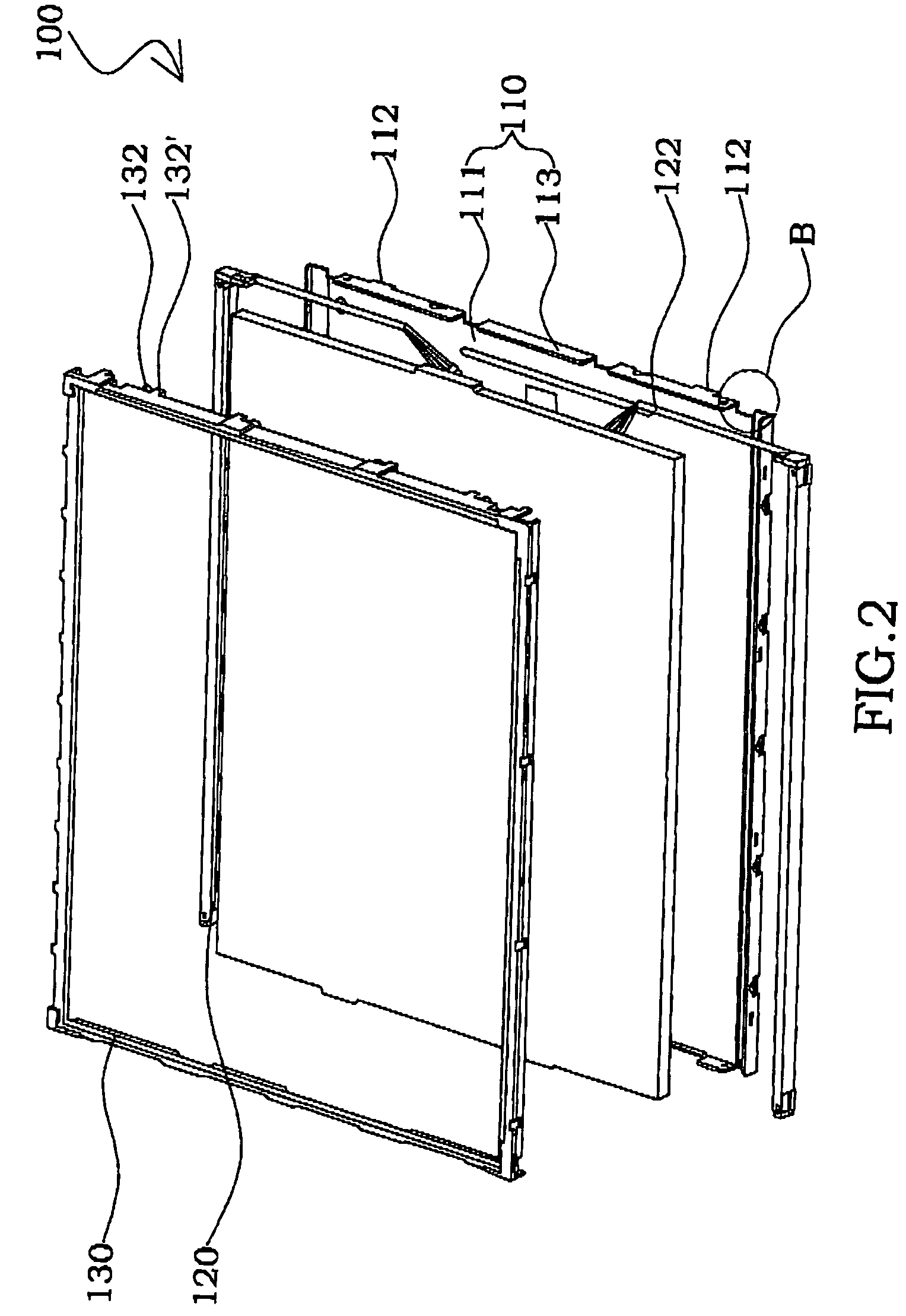
[0016]FIG. 2 is a schematic exploded view of the architecture of the backlight module of an embodiment in accordance with the present invention. In the embodiment, the backlight module 100 includes a rear frame 110, a light source 120, and a mold frame 130. Wherein the rear frame 110 and the mold frame 130 can be engaged with each other so as to fix the light source 120 and the lamp cable 122 thereof. Such as shown in FIG. 2, the rear frame 110 is made of the metal materials and has a plurality of protrusions 112 in the appropriate position, for example the side edge 111 of the rear frame 110. In one embodiment, the rear frame 110 further includes a base plate 113. The light source 120 is arranged above the rear frame 110, and has a lamp cable 122 led out from the leading-out area B of the rear frame 110. In order to prevent the damage of the lamp cable 122 from the rear frame 110, any one of a heat shrinkable tube and an insulating materials can be utilized to cover the lamp cable ...


PUM


Abstract

A cables fixing apparatus for backlight a module includes a rear frame having a leading-out area in a side edge with a plurality of protrusions thereof; a lamp cable; and a mold frame having a plurality of crooks, wherein these crooks face to any one of these protrusions so as to define a cable groove to fix the lamp cable. These protrusions of the rear frame and these crooks of the mold frame are utilized to arrange and fix the lamp cable in the cable groove to avoid the fracturing problem of solder joint of lamp and prevent the interference as assembling because of the displacement issue of the lamp cable.

Description

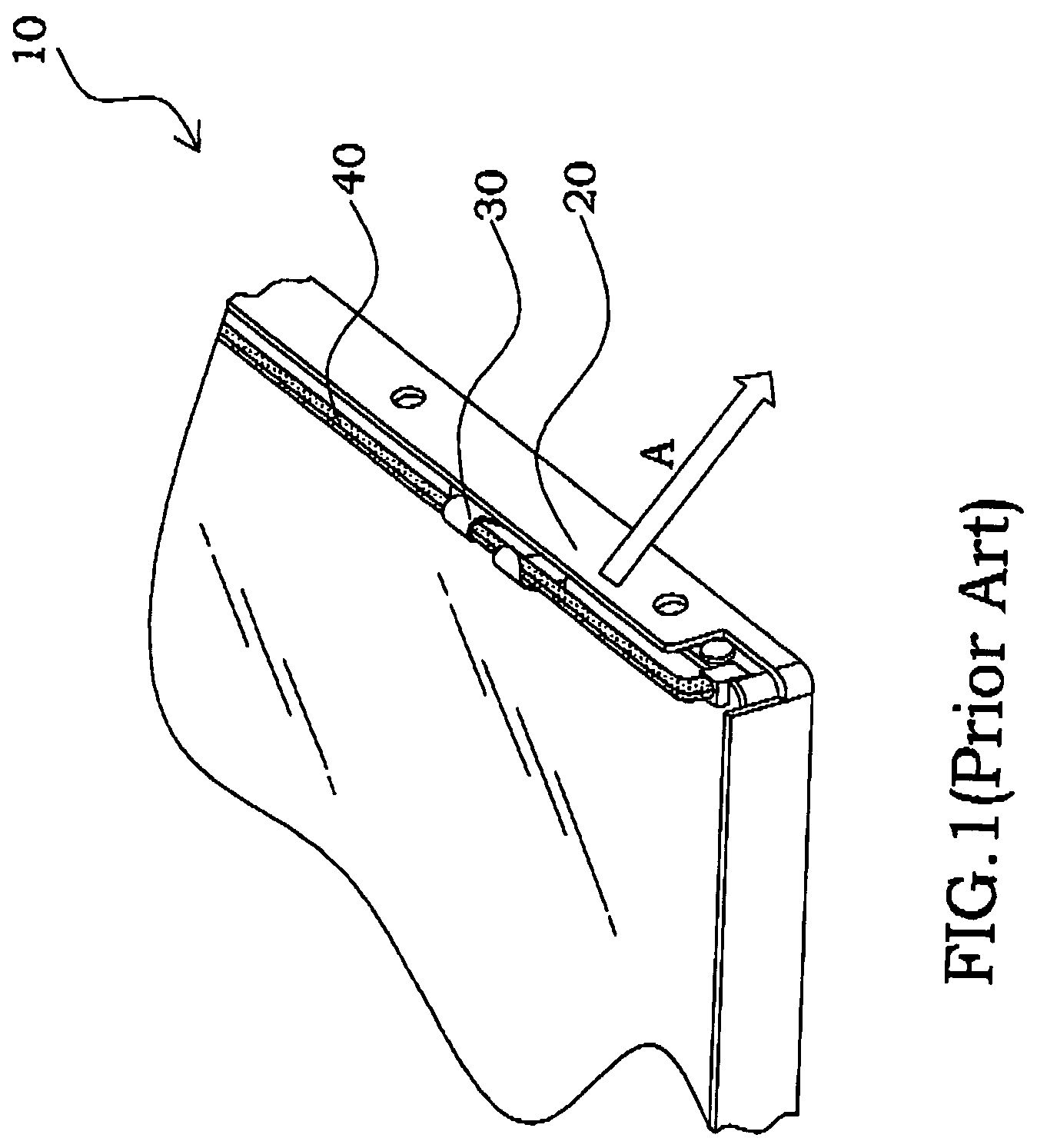
BACKGROUND[0001]1. Field of the Invention[0002]The present invention generally relates to a backlight module, and more especially, to a cables fixing apparatus for the backlight module.[0003]2. Description of the Prior Art[0004]Recently, liquid crystal display (LCD) has been utilized widely. With the improvement of the drive technology of LCD, the LCD has the features of low power consumption, thin type, and low drive voltage, and has been widely used on mobile telecommunication apparatus, notebook, desktop display, and any kind of the projection equipments. One of the most commonly used LCD is thin-film transistor (TFT) LCD. Because the TFT LCD dose not illuminate itself, the backlight module is utilized to provide a light source to the TFT LCD. No matter what kind of the light source is used, the wire of the backlight module must be let out from the leading-out area thereof during the backlight module assembly process so as to connect with the power supply.[0005]Generally speaking...

Claims


Application Information

Patent Timeline
Patent Type & Authority Patents(United States)
IPC IPC(8): F21V7/04
CPCG02F1/133608F21V27/00G02F2001/133612G02F1/133612
Inventor HSU, WEI-CHEN
Owner CHUNGHWA PICTURE TUBES LTD
Learn More