
Breast pump

a breast pump and pump body technology, applied in the field of breast pump, can solve the problems of backflow milk and mist-form milk infiltrating, and achieve the effect of easy operation

Active Publication Date: 2010-05-11
PIGEON CORP
View PDF4 Cites 5 Cited by
  • Summary
  • Abstract
  • Description
  • Claims
  • Application Information

AI Technical Summary

Benefits of technology

The present invention is about a breast pump that can be easily disassembled for cleaning and assembled again easily. The breast pump includes a storage container for storing milk, an attachment / detachment portion for attaching and detaching the breast pump main body, and an operating means or operator structure for deforming a negative pressure generating member. The negative pressure generating member includes a joint portion, an engagement opening, and a deforming portion. The engagement opening allows for easy attachment and detachment of the operating means or structure, and the deforming portion allows for negative pressure generation without the need for a hard recess or recess that could collect milk residue and make the breast pump unhygienic. The engagement opening includes an insertion opening portion and a holding opening portion, which ensures that the joint portion remains in place during operation. The invention provides a solution for improving the hygiene and ease of use of breast pumps.

Problems solved by technology

However, in these breast pumps, backflow milk and mist-form milk may infiltrate the recess or recessed portion housing the deforming portion such as the diaphragm.

Method used


Image

  • Breast pump
  • Breast pump
  • Breast pump

Examples


Embodiment Construction

[0034]Exemplary embodiments of the presently disclosed subject matter will be described in detail below with reference to the attached drawings.

[0035]Note that the embodiments to be described below are specific examples of the presently disclosed subject matter, and therefore include various technical features and characteristics. However, it should be understood that the scope of the presently disclosed subject matter is not limited to these embodiments.

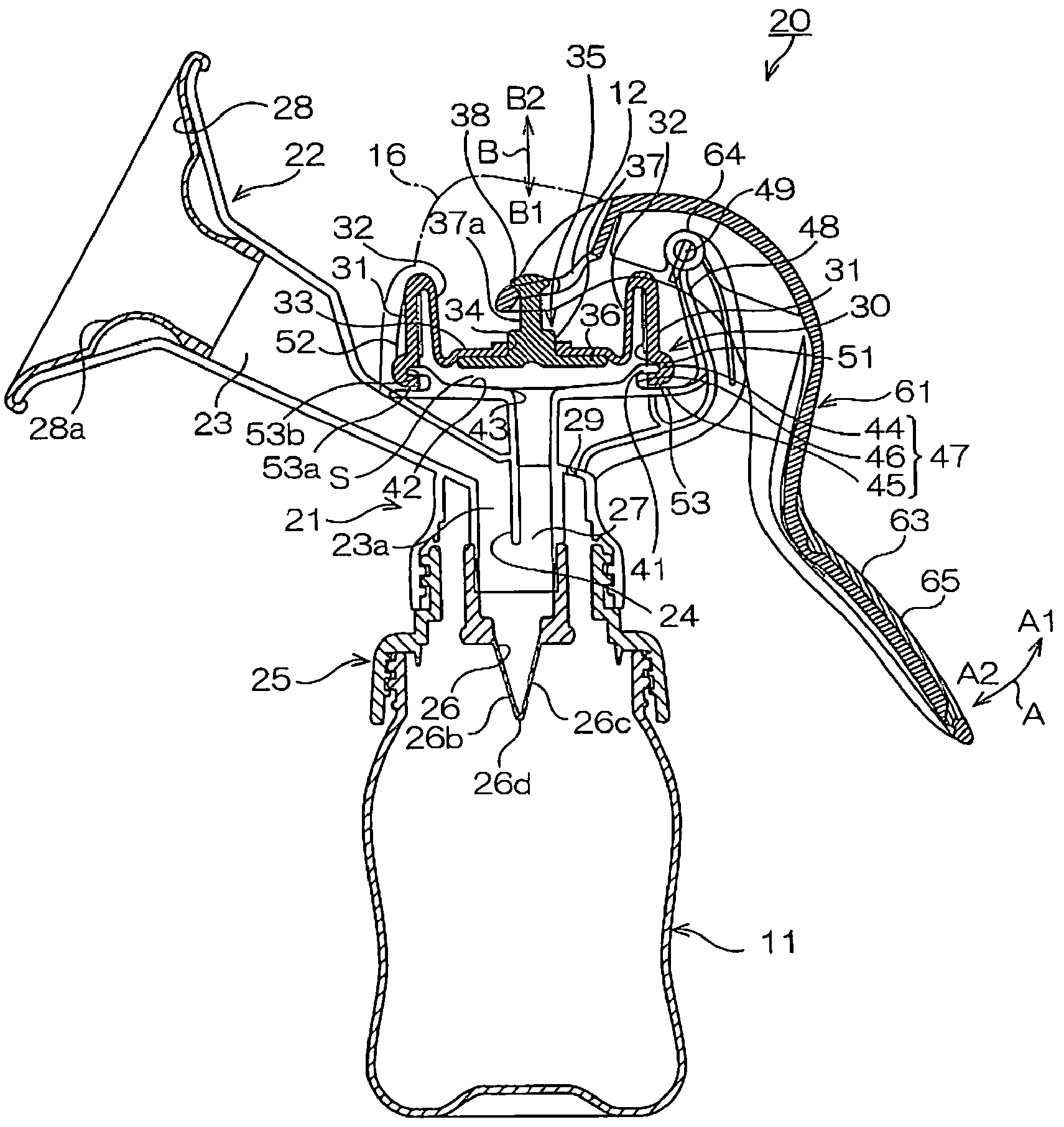
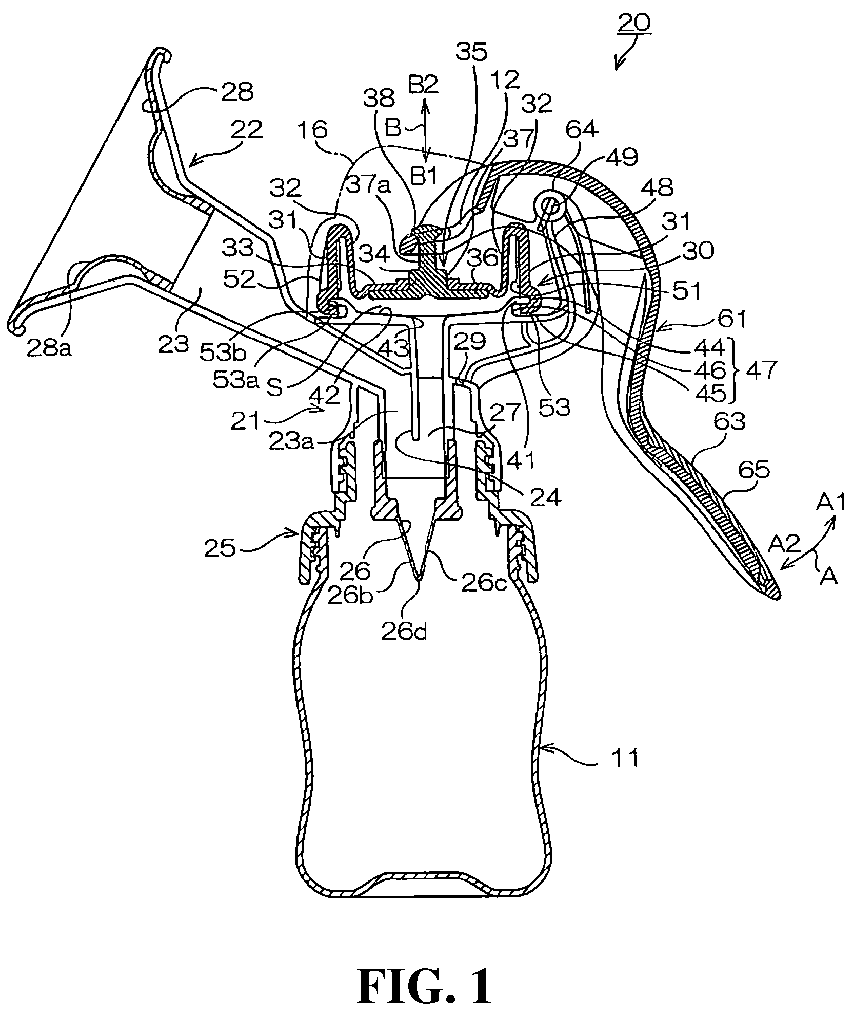
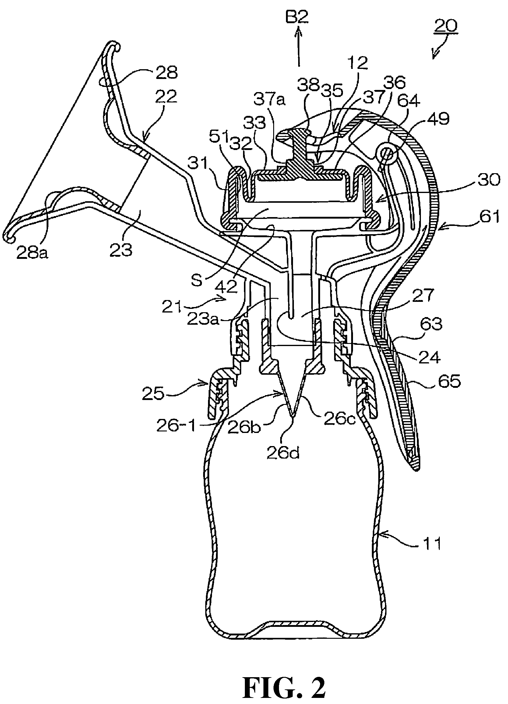
[0036]FIGS. 1 and 2 are schematic sectional views showing an example of a breast pump according to an embodiment of the presently disclosed subject matter.

[0037]A breast pump 20 can include a breast pump main body 21 (to be referred to as the “main body” hereafter), a handle 61 serving as operating means, and a bottle 11 serving as a storage container for storing expressed milk. The handle 61 can be attached to and detached from the breast pump main body 21.

[0038]Further, as shown in FIG. 1, a substantially dome-shaped hood 16 is de...


PUM


Abstract

A breast pump can be configured such that is can be easily dismantled for cleaning and easily re-assembled and is formed such that an operator or operating means thereof do not easily become detached during operation. The breast pump can include a storage container for storing milk, a breast pump main body, and an operator or operating means attached to the breast pump main body for deforming a negative pressure generating member attached to the breast pump main body. The operator can take the form of a lever, and can have an engaged portion that is engaged to an engagement portion on the breast pump main body side and includes an engagement opening formed on one end side of the operator. The engagement opening can include an insertion opening portion that is formed adjacent a bearing portion side and is larger than the outer form of the engagement portion, and a holding opening portion that is coextensive with the insertion opening portion but further toward the tip end side than the insertion opening portion. The holding opening can be smaller than the outer perimeter of the engagement portion.

Description

[0001]This application claims the priority benefit under 35 U.S.C. §119 of Japanese Patent Application No. 2007-29350 filed on Feb. 8, 2007, which is hereby incorporated in its entirety by reference.BACKGROUND[0002]1. Technical Field[0003]The presently disclosed subject matter relates to an improvement in a breast pump that is capable of milking and which uses manually or mechanically driven operator structures or means, for example.[0004]2. Description of the Related Art[0005]Breast pumps having a horn-shaped milking portion with an enlarged diameter that is brought into contact with the breast of a mother, or in other words an enlarged-diameter milking portion, are widely used.[0006]In a well-known constitution for ensuring that the milk, which is formed into a mist by negative pressure generated during milking, does not leak out, a recess is provided in an upper end of a breast pump main body or the like and a deformable member such as a diaphragm is housed in the recess.[0007]Mo...

Claims


Application Information

Patent Timeline
Patent Type & Authority Patents(United States)
IPC IPC(8): A61M1/06
CPCA61M1/06A61M1/066A61M1/0072A61M2205/075A61M1/82
Inventor KATAOKA, SHINICHITASHIRO, MITSUO
Owner PIGEON CORP
Learn More