
Water treating apparatus

a technology of water treatment apparatus and water treatment chamber, which is applied in the direction of multi-stage water/sewage treatment, membranes, separation processes, etc., can solve the problem that the vertical hollow fiber membrane module cannot be installed at a place with a low ceiling, and achieve the effect of efficient installation and smooth pulling ou

Inactive Publication Date: 2010-05-04
ECO CREATIVE JAPAN
View PDF7 Cites 8 Cited by
  • Summary
  • Abstract
  • Description
  • Claims
  • Application Information

AI Technical Summary

Benefits of technology

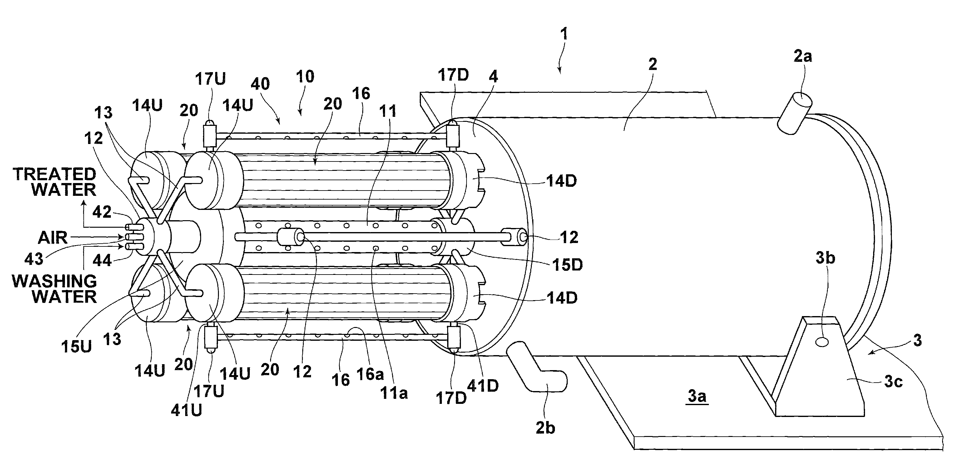
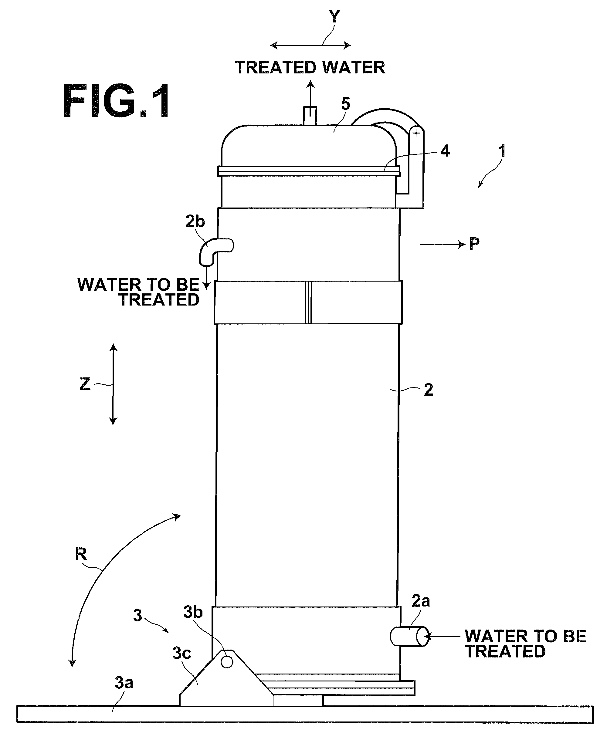
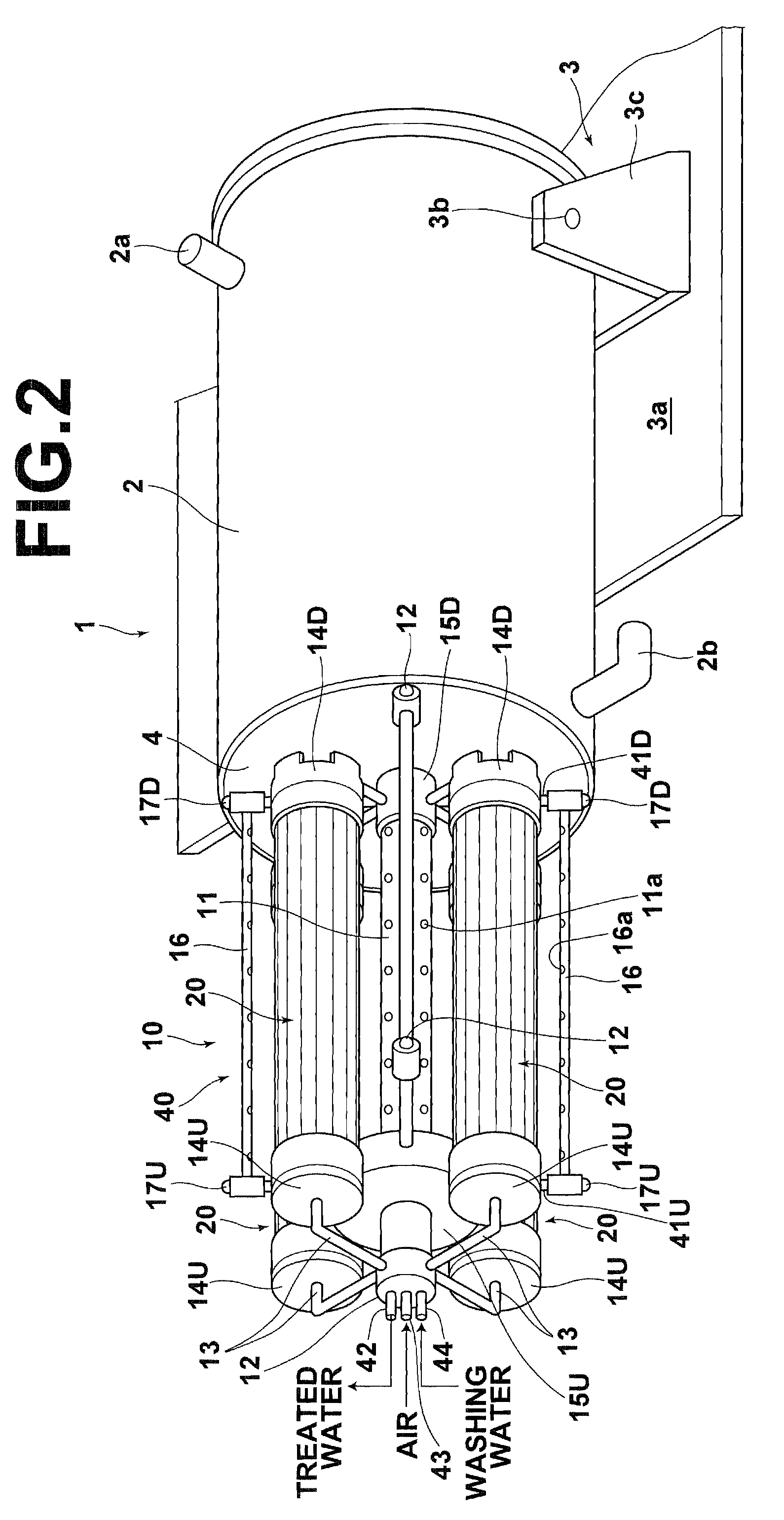
[0012]According to the water treating apparatus of the invention, a housing for receiving water to be treated fed thereto; a membrane module unit for applying filtration treatment to the water to be treated in the housing and extracting treated water, the membrane module unit being contained in the housing such that the membrane module unit can be pulled out from the housing; and a housing holder for holding the housing tiltably between a position where the longitudinal direction of the membrane module unit is substantially vertical and a position where the longitudinal direction of the membrane module unit is substantially horizontal are provided. This allows the housing to be tilted to the horizontal position and the membrane module to be pulled out in the horizontal direction for removing the membrane module from the housing, thereby eliminating need of enough space above the housing for the membrane module pulled up from the housing. Therefore, the water treating apparatus using the vertical membrane module can be installed even at a place with a low ceiling. Further, in a case where the water treating apparatus is newly installed at a place with a low ceiling, the housing holder 3 can be disposed on the ground with the longitudinal direction of the housing 2 being horizontal, and then the longitudinal direction of the housing 2 can be set in the vertical direction. Thus, the water treating apparatus can be efficiently installed without necessitating conventional extensive installation work, such as making a hole in the ceiling and installing the water treating apparatus though the hole.
[0013]If the membrane module unit includes a membrane module, a holder for holding the membrane module, and abutting members provided at the holder, which abut on the inner wall surface of the housing and are movable on the inner wall surface, then the membrane module unit is pulled out from the housing with being supported by the abutting members when the membrane module is to be removed from the housing, and therefore the membrane module unit can be smoothly pulled out. Further, when the housing is tilted, movement of the membrane module within the housing is limited by the abutting members, thereby preventing the membrane module from being damaged by contacting the inner wall surface of the housing.

Problems solved by technology

This necessitates an enough space between the housing and the ceiling for accommodating the pulled out cartridge, and therefore the vertical hollow fiber membrane module may not be installed at a place with a low ceiling.

Method used


Image

  • Water treating apparatus
  • Water treating apparatus
  • Water treating apparatus

Examples


Embodiment Construction

[0026]Hereinafter, a preferred embodiment of a water treating apparatus of the present invention will be described in detail with reference to the drawings. FIG. 1 shows the appearance of the water treating apparatus of the preferred embodiment of the invention, FIG. 2 is a perspective view showing a membrane module unit 13 pulled out from a housing 2, and FIG. 3 is a schematic diagram showing the membrane module unit 10 viewed from the side of an opening 4 of the housing 2. Now, the water treating apparatus 1 will be described with reference to FIGS. 1 to 3.

[0027]The water treating apparatus 1 applies filtration treatment to water to be treated, such as organic wastewater, using the vertical membrane module and extracts treated water. The water treating apparatus 1 includes: a housing 2 containing the membrane module unit 10 and having the opening 4 at the top, through which the membrane module unit 10 is pulled out; and a housing holder 3 connected to the lower portion of the hous...


PUM

PropertyMeasurementUnit
lengthaaaaaaaaaa
outer diameteraaaaaaaaaa
pressureaaaaaaaaaa

Abstract

A vertical membrane module unit is allowed to be installed even at a place with a low ceiling. A housing containing a vertical membrane module unit is held by a housing holder. The housing holder holds the housing tiltably such that the housing can be positioned with the longitudinal direction of the membrane module unit being substantially vertical when treated water is extracted, and the housing can be positioned with the longitudinal direction of the membrane module unit being substantially horizontal when the membrane module unit is removed from the housing.

Description

BACKGROUND OF THE INVENTION[0001]1. Field of the Invention[0002]The present invention relates to a water treating apparatus for treating water using a hollow fiber membrane module.[0003]2. Description of the Related Art[0004]In water treating apparatuses for treating organic wastewater, sewage water or other wastewater, a method is used wherein a hollow fiber membrane module is contained in a housing, and filtration treatment is carried out using the hollow fiber membrane module. Various structures have been proposed for the hollow fiber membrane module. Among them, a so-called vertical hollow fiber membrane module, which is structured to be disposed in a housing such that the longitudinal direction of the hollow fiber membrane module is vertical, may sometimes be used.[0005]When the above-described vertical hollow fiber membrane module is to be replaced or checked, the hollow fiber membrane module is typically pulled upward in the vertical direction to be removed from the housing. ...

Claims


Application Information

Patent Timeline
Patent Type & Authority Patents(United States)
IPC IPC(8): B01D35/30B01D25/00B01D29/50B01D29/00
CPCB01D61/18B01D61/20B01D63/043B01D65/02C02F1/444B01D2313/02B01D2313/56B01D2313/20B01D2313/26B01D2321/18B01D2321/30B01D2313/06B01D2313/205B01D2313/57
Inventor KOBAYASHI, MASATO
Owner ECO CREATIVE JAPAN
Learn More