
Transmission for motorized track system

a technology of motorized track and transmission housing, which is applied in the direction of movable seats, gearing, hoisting equipment, etc., can solve the problems of lateral movement of the components within the transmission housing, shim disks subject to manufacturing variances, and not consistently addressing noise problems

Inactive Publication Date: 2010-04-27
ADIENT LUXEMBOURG HLDG SARL
View PDF16 Cites 23 Cited by
  • Summary
  • Abstract
  • Description
  • Claims
  • Application Information

AI Technical Summary

Benefits of technology

"The invention provides a transmission assembly for a motorized track system used to adjust the position of a supported element such as a vehicular seat, window or the like. The assembly includes an externally threaded lead screw, a drive nut, and a housing. A compressible washer is placed between the drive nut and the housing to dampen or eliminate noise producing vibrations from the transmission. The invention also provides a method for eliminating play between the drive nut and the worm gear by using a wave washer. The technical effects of the invention are improved stability and reduced noise in the motorized track system."

Problems solved by technology

Because certain components within the transmission rotate while others are held generally stationary, vibrations may be produced within the transmission when the transmission is operational, thereby causing noise.
Another cause of noise is lateral movement of the components within the transmission housing.
Shim disks are subject to manufacturing variances, however and may not consistently address the noise issues.

Method used


Image

  • Transmission for motorized track system
  • Transmission for motorized track system
  • Transmission for motorized track system

Examples


Embodiment Construction

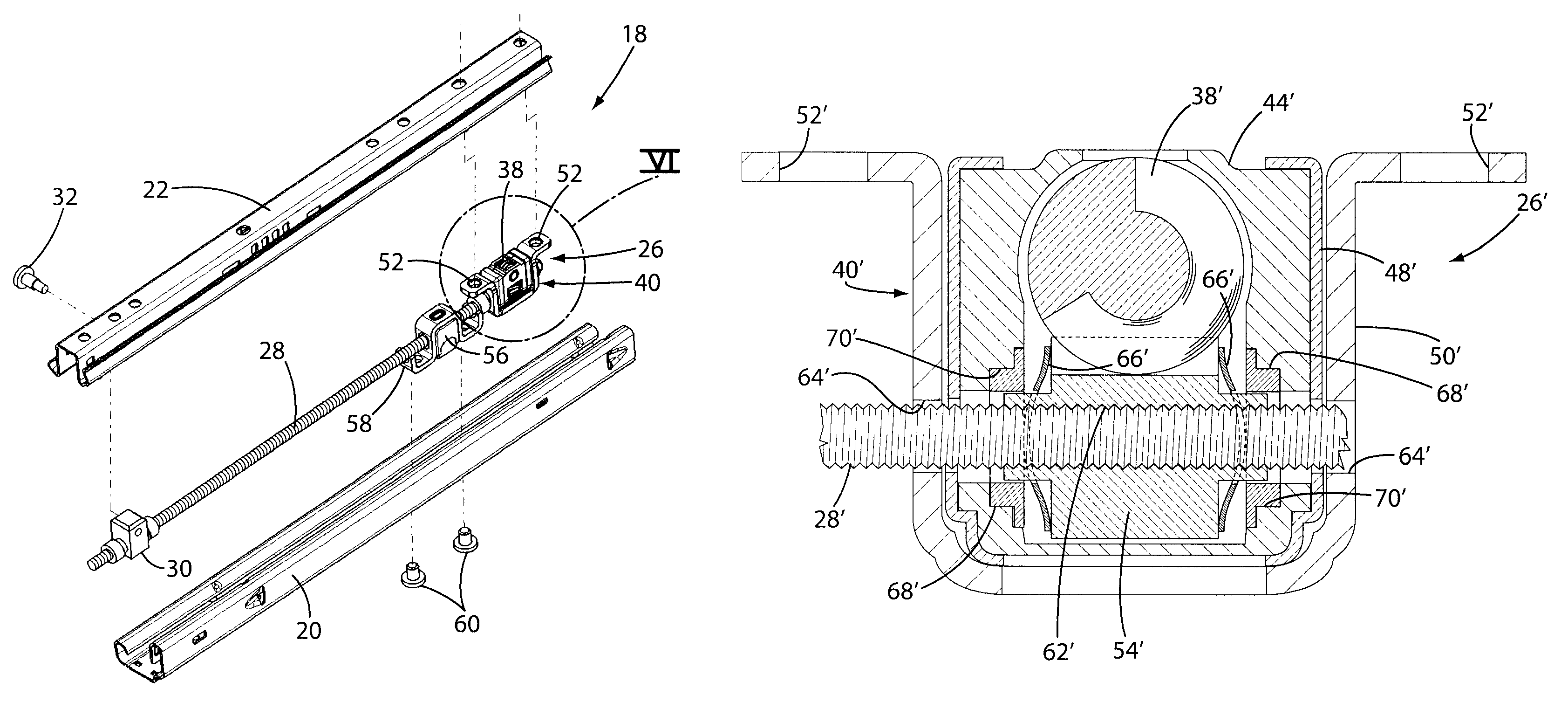
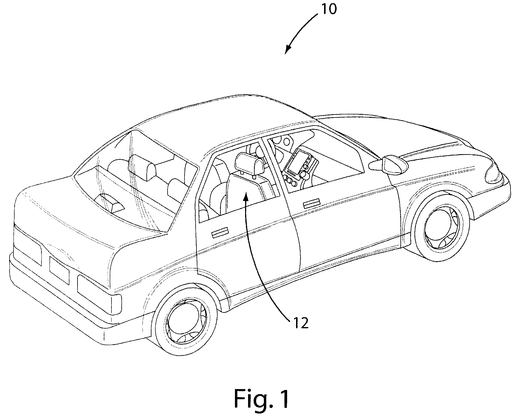
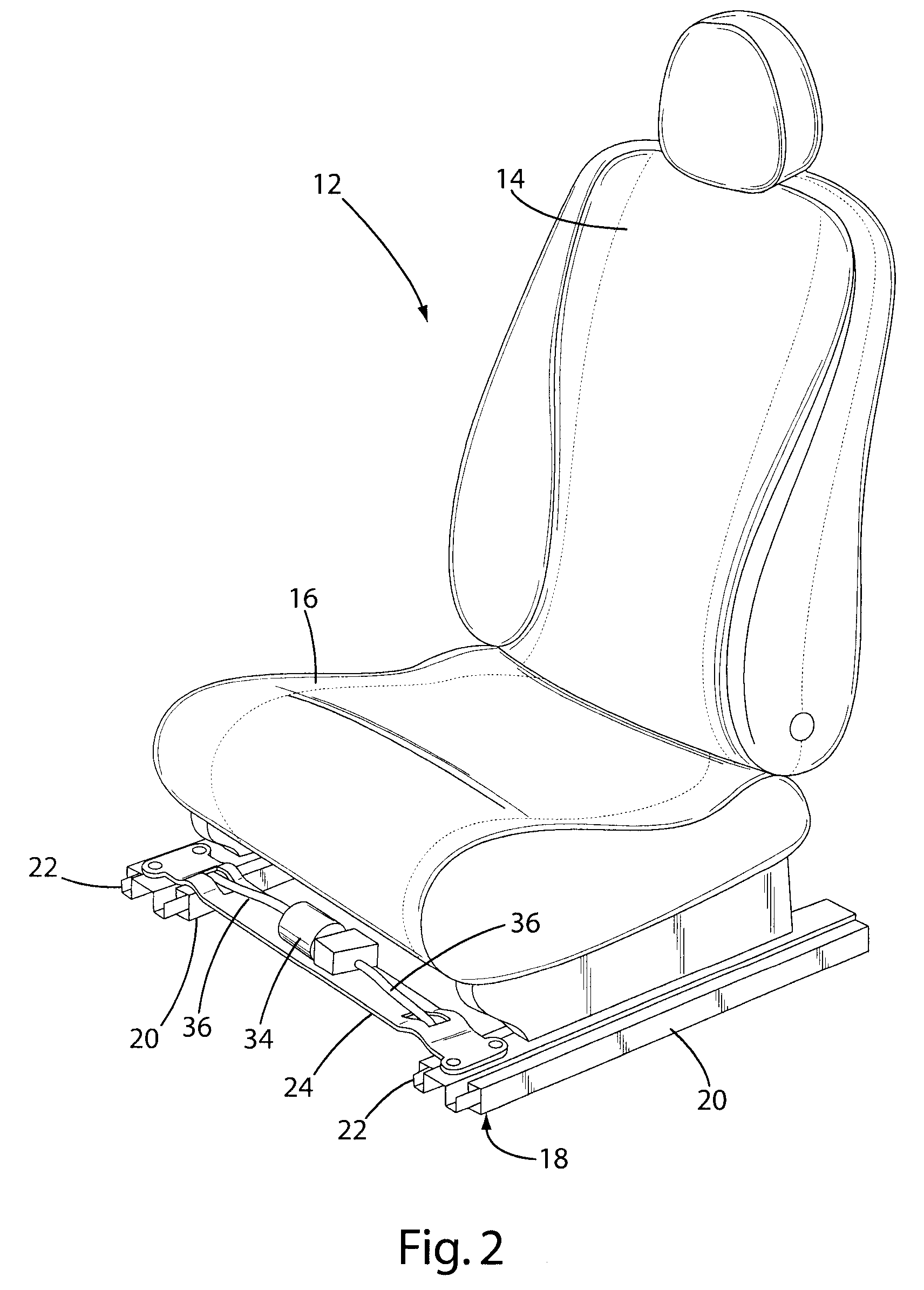
[0022]Referring to the Figures, wherein like numerals indicate like or corresponding parts throughout the several views, an exemplary motor vehicle is generally shown at 10 in FIG. 1. The vehicle 10 in FIG. 1 is merely exemplary, and may instead take the form of a light duty truck, SUV, minivan, bus, train, airplane, boat, or any other such vehicle or stationary application in which a motorized track assembly may be employed. In this specific example, however, the vehicle 10 is depicted including a passenger seat 12 having the customary back rest 14 and seat cushion 16, as illustrated in FIG. 2. The seat 12 is supported above a motorized track system, generally indicated at 18, that is configured to allow an occupant to adjust the position of the seat 12 in longitudinally forward and rearward directions relative to the vehicle 10. Although the following description of the subject invention is carried out by reference to vehicular seating application, it will be understood by those o...


PUM


Abstract

A track system (18) of the type used to adjust the position a supported element such as vehicular seat (12) includes a pair of base rails (20) that slidably interact with a respective pair of driven rails (22). A transverse rail (24) is attached to each of the driven rails (22) so that the driven rails (22) slide together as a unit. A motor (34) is supported on the transverse rail (24) and includes a pair of drive shafts (36) emanating from either end. The drive shafts (36) carry on their distal ends' respective worm gears (38) which are contained within a transmission assembly (26). The worm gears (38) mesh with external teeth on respective drive nuts (54) which interact with a lead screw (28) that can be oriented to either remain stationary relative to the base rails (20) or can be rotatably fixed within the driven rails (22). The drive nut (54) is prevented from causing objectionable noise and premature wear in operation by the inclusion of one or two compressible washers (66).

Description

CROSS REFERENCE TO RELATED APPLICATIONS[0001]This Application claims priority to U.S. Provisional Application No. 60 / 878,712 filed Jan. 4, 2007.BACKGROUND OF THE INVENTION[0002]1. Field of the Invention[0003]This invention relates generally to a motorized track system, and more particularly toward a transmission for a motorized track system of the type used in position adjustors for vehicular seats, windows and the like.[0004]2. Related Art[0005]Vehicle seat assemblies are often provided with a motorized track system that enable the position of the seat assembly within a motor vehicle to be adjusted in the forward and rearward directions. Similarly, vehicular window assemblies may include a motorized track system of similar construction to enable the position of the window to be adjusted in up and down directions. In each case, the supported element is guided by the motorized track system for back and forth movement to change its position, as desired.[0006]In the case of vehicular s...

Claims


Application Information

Patent Timeline
Patent Type & Authority Patents(United States)
IPC IPC(8): F16H55/18B60N2/90
CPCB60N2/067F16H25/2021F16H2025/209B60N2002/024Y10T74/18728Y10T74/18792Y10T74/19828Y10T74/19898Y10T74/19902B60N2/02258B60N2/02F16H27/02F16H29/02F16H1/16
Inventor PORINSKY, LUCAS P.TIGHE, WILLIAM R.HUFFMAN, WILLIAM M.
Owner ADIENT LUXEMBOURG HLDG SARL
Learn More