
Traction device

a technology of traction device and instep, which is applied in the direction of fastenings, uppers, bootlegs, etc., can solve the problems of not being able to provide sufficient stability for extended use on inclined surfaces, devices are not effective on wet rocks, and are often complicated in structure, so as to maintain a downward pressure on the instep region of the boot.

Inactive Publication Date: 2010-04-27
BURGESS RICHARD C
View PDF18 Cites 32 Cited by
  • Summary
  • Abstract
  • Description
  • Claims
  • Application Information

AI Technical Summary

Benefits of technology

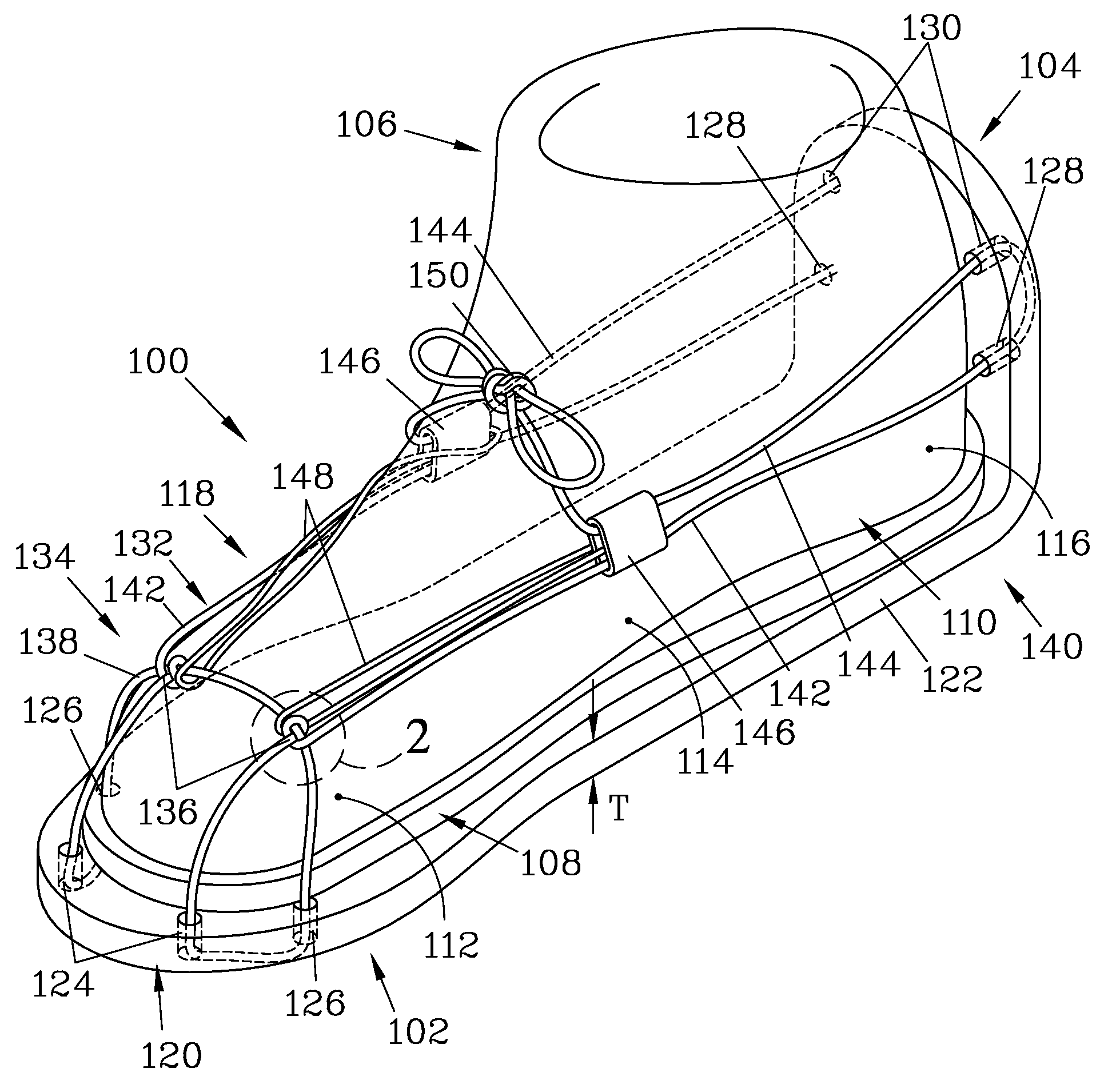
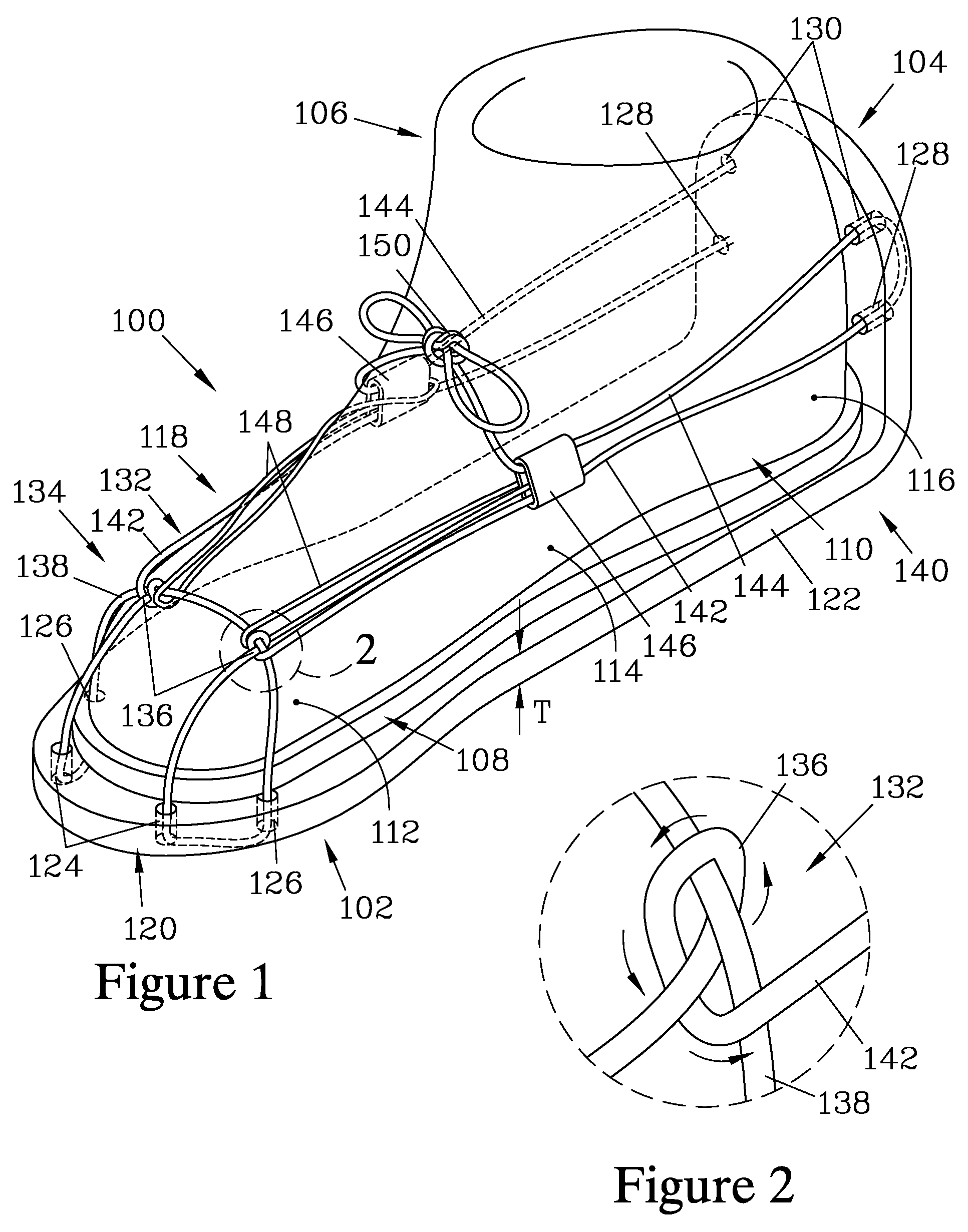
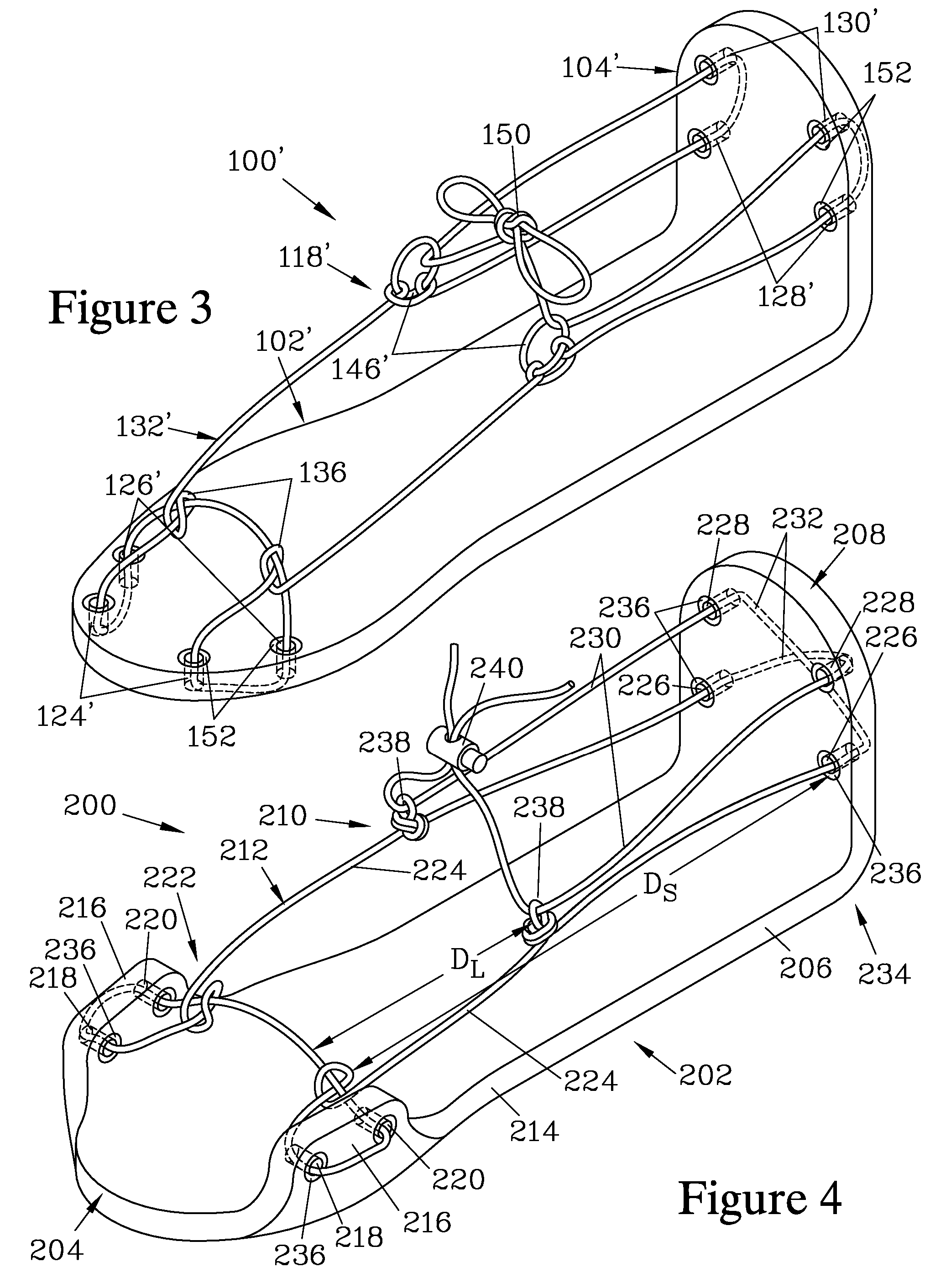
"The present invention is a traction device for boots or shoes that increases the traction provided to the wearer. The device is designed to be used on boots with a sole section and an upper section. The sole section has an arch region for the support of the arch of the wearer. The upper section has a toe region and a heel region. The device has a felt platform with a toe section and a heel section, with passages for the toe and heel regions. The toe section has ear extensions that extend between the body of the platform and the toe region of the boot. The heel section has a heel extension that extends therefrom a sufficient distance to bring it in contact with the heel region of the upper section of the boot. The device also has cording that is threaded through the toe and heel sections and forms side stringers and cord extension segments to maintain a downward pressure on the instep region of the boot. The cording can be secured with a cordlock. The device is designed to better conform to the contour of a hiking boot by shaping the felt platform and heel extension to match the contour of the boot."

Problems solved by technology

For ice, such devices frequently employ downward-protruding cleats or caulks to provide greater traction; however, such devices are not effective on wet rocks.
While such devices may be effective for limited use on relatively flat surfaces, such as ice, the bindings may not provide sufficient stability for extended use on inclined surfaces, such as when hiking on rocky terrain.
Furthermore, such devices are frequently complicated in structure, making them expensive to fabricate and / or difficult to attach to and detach from the footwear.
Additionally, since the soles of such boots are typically of stiff, noncompliant material, they provide very little traction.

Method used


Image

  • Traction device
  • Traction device
  • Traction device

Examples


Embodiment Construction

[0022]FIG. 1 is an isometric view of a traction device 100 which forms one embodiment of the present invention. The traction device 100 has a felt platform 102 with a heel extension 104 attached thereto. In this embodiment, the felt platform 102 and the heel extension 104 are formed from a single piece of felt material. The felt material is preferably a polyester woven felt material, such as is commercially available, and has a thickness T that is preferably between about ⅛″ and ½″. The thinner felt materials are felt to be suitable when the traction device 100 is to be used on ski boots, while greater thickness materials are preferred for use with hiking boots in order to provide greater durability and shock absorption. ⅜″ has been found to be a thickness well suited for use with hiking boots.

[0023]The traction device 100 is shown engaged with a boot 106 that has a sole section 108 and an upper section 110. The upper section 110 includes a toe region 112, an instep region 114, and ...


PUM


Abstract

A traction device for a boot has a felt platform with a toe section and a heel section, and a heel extension attached to the heel section. Cording passes through two pairs of passages in each of the toe section and the heel extension. On each side, the cording passing from a toe section passage to a heel extension passage forms a side stringer, and the cord extending beyond the heel extension forms a cord extension segment. Loops are provided on each side stringer, and the cord extension segments are each passed through one of the loops before being cinched to tighten the cording against the boot. Preferably, a single length of cord is employed and the loops are tied into the side stringers. It is also preferred for the toe section passages to be positioned on ear extensions that protrude from a body of the felt platform.

Description

FIELD OF THE INVENTION[0001]The present invention relates to a device which can be secured to a conventional shoe or boot to cover the sole thereof in order to improve traction on slippery surfaces.BACKGROUND OF THE INVENTION[0002]It has long been known to attach an auxiliary sole or slipper onto footwear so as to change the characteristic of the sole of the footwear. Most commonly, the auxiliary device provides additional traction on slippery surfaces such as ice or wet rocks. For ice, such devices frequently employ downward-protruding cleats or caulks to provide greater traction; however, such devices are not effective on wet rocks. One material which has classically been used for providing traction on wet rocks is felt, such as taught in U.S. Pat. No. 3,099,885. Auxiliary felt soles which can be attached to conventional footwear as needed are taught in U.S. Pat. Nos. 1,187,778 and 5,150,536. Auxiliary soles having a cushion material such as felt may also be employed to provide a ...

Claims


Application Information

Patent Timeline
Patent Type & Authority Patents(United States)
IPC IPC(8): A43B3/10A43C11/00A43C15/00
CPCA43B5/0419A43B13/36A43C15/066A43C15/06A43C15/02
Inventor BURGESS, RICHARD C.
Owner BURGESS RICHARD C
Learn More