
Memory device including 3-dimensionally arranged memory cell transistors and methods of operating the same

a memory cell transistor and memory device technology, applied in semiconductor devices, digital storage, instruments, etc., can solve the problems of increasing the integration level of semiconductor devices, incurring enormous costs, and limited channel length of cell transistors

Active Publication Date: 2010-04-20
SAMSUNG ELECTRONICS CO LTD
View PDF21 Cites 31 Cited by
  • Summary
  • Abstract
  • Description
  • Claims
  • Application Information

AI Technical Summary

Benefits of technology

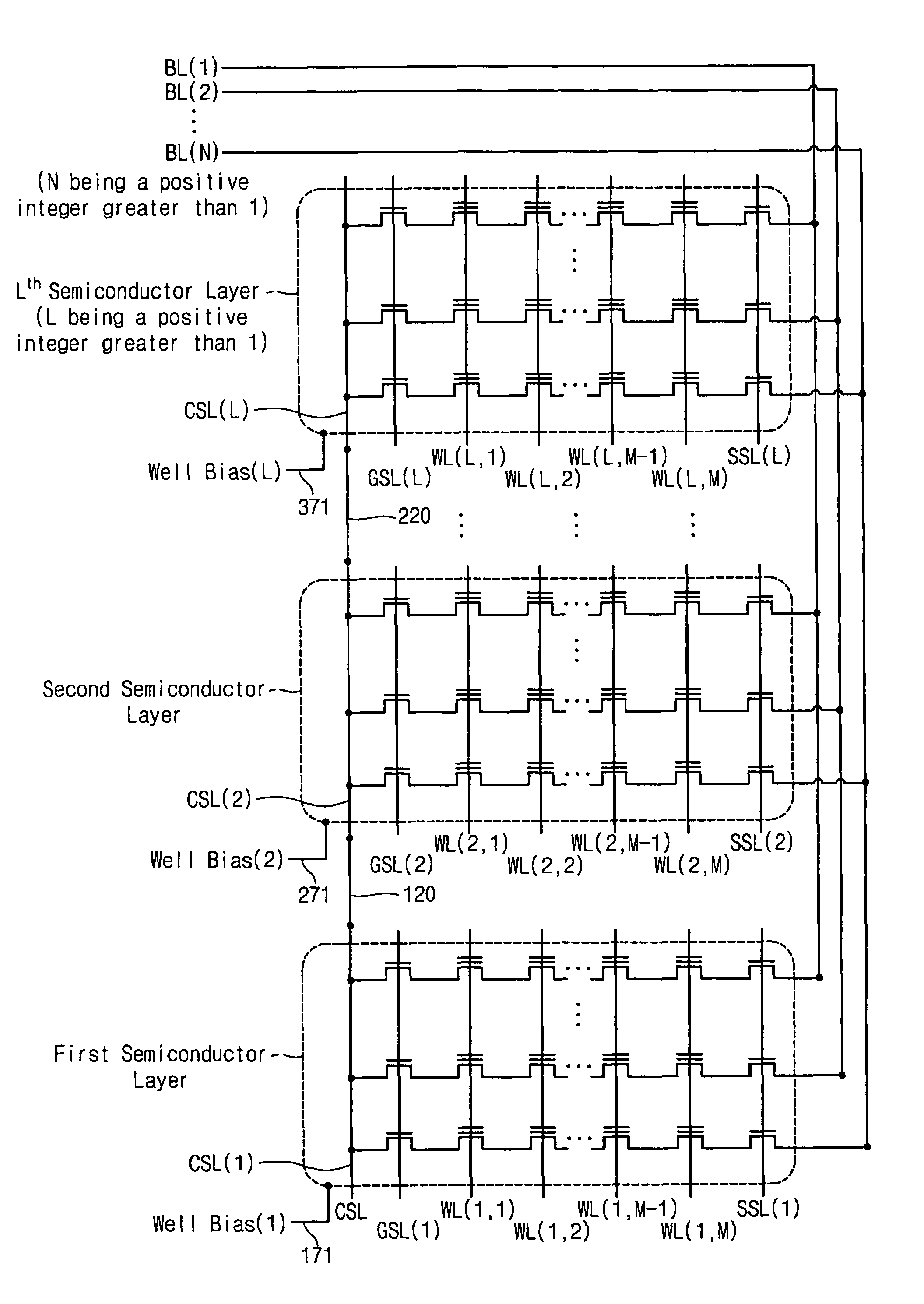
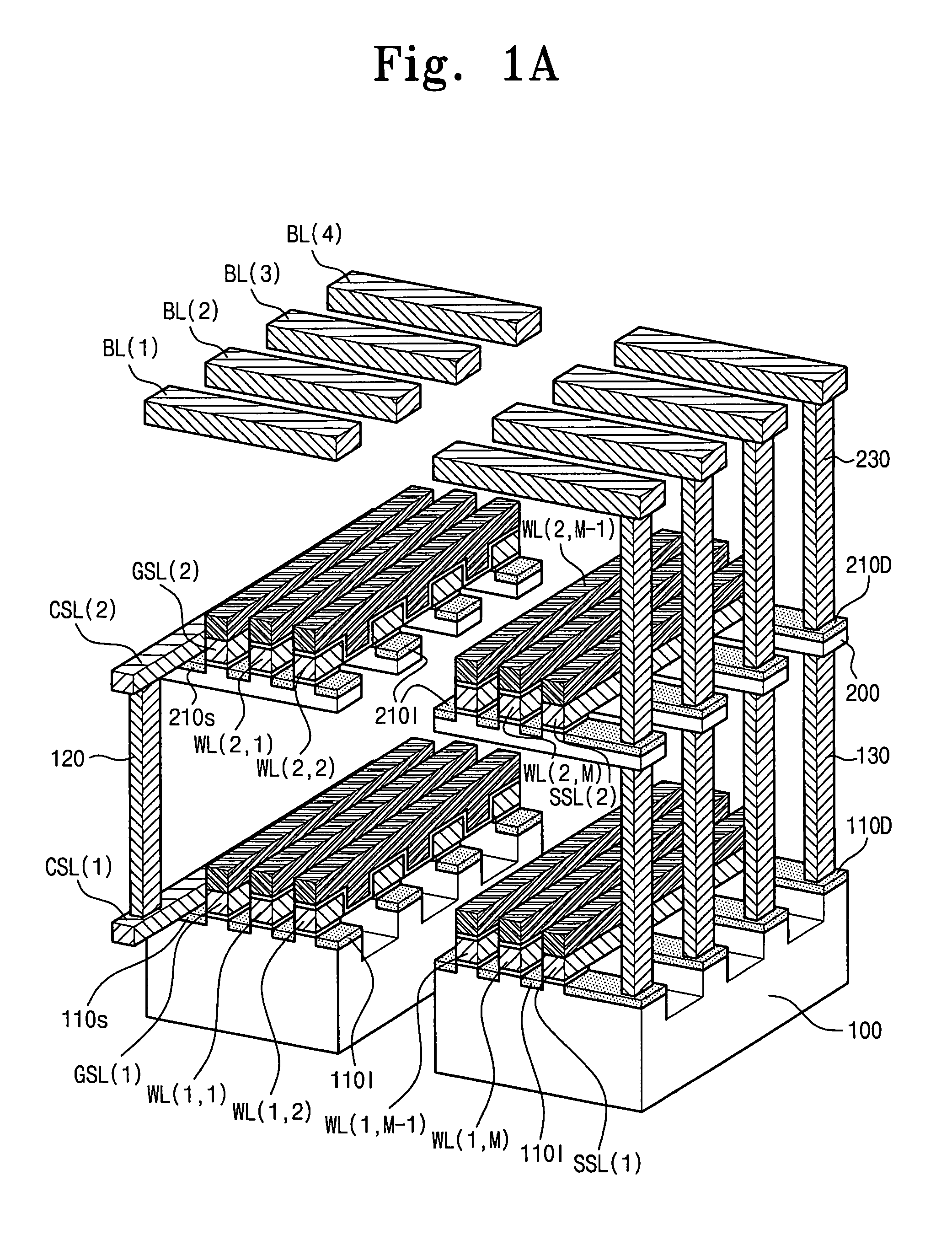
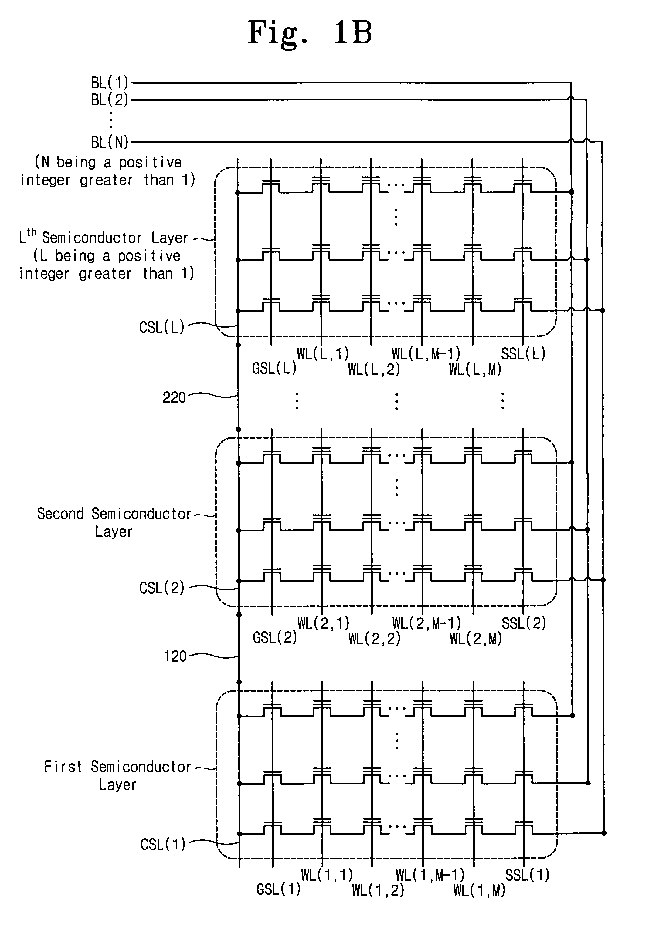
This patent is about a memory device that has multiple layers of semiconductor material, each with a gate structure and bitlines. The layers are stacked, and the bitlines run across the gate structures. There are also common source lines that are connected to each other, so they all have the same potential. The technical effect of this design is that it allows for more efficient and reliable memory reading and writing.

Problems solved by technology

Increases in the integration level of semiconductor devices are limited because the development of advanced processing technologies incurs enormous expense and longer time.
In spite of the restrictions in advancing techniques for forming finer patterns, a reduction of the channel length of a cell transistor is limited by an issue of leakage current for semiconductor devices, e.g., flash memory devices.
However, the unintended leakage current of the cell transistor increases with a decrease in size of the cell transistor.
The leakage current makes determining whether the cell transistor of the flash memory is programmed more difficult.
However, conventional NAND flash memory devices suffer from not only the limitation resulting from leakage current but also from the limitation of a lower sensible current which interferes with an increase in integration level.
Therefore, the limitation of the lower sensible current makes reducing the area occupied by the selection transistors in the NAND flash memory more difficult.

Method used


Image

  • Memory device including 3-dimensionally arranged memory cell transistors and methods of operating the same
  • Memory device including 3-dimensionally arranged memory cell transistors and methods of operating the same
  • Memory device including 3-dimensionally arranged memory cell transistors and methods of operating the same

Examples


Embodiment Construction

[0015]Example embodiments will now be described more fully hereinafter with reference to the accompanying drawings. Embodiments may, however, be in many different forms and should not be construed as being limited to the example embodiments set forth herein. Rather, these example embodiments are provided so that this disclosure will be thorough and complete, and will fully convey the scope to those skilled in the art. In the drawings, the thicknesses of layers and regions may be exaggerated for clarity.

[0016]It will be understood that when a component is referred to as being “on,”“connected to” or “coupled to” another component, it can be directly on, connected to or coupled to the other component or intervening components may be present. In contrast, when a component is referred to as being “directly on,”“directly connected to” or “directly coupled to” another component, there are no intervening components present. As used herein, the term “and / or” includes any and all combinations...


PUM


Abstract

A memory device may include L semiconductor layers, a gate structure on each of the semiconductor layers, N bitlines, and / or a common source line on each of the semiconductor layers. The L semiconductor layers may be stacked, and / or L may be an integer greater than 1. The N bitlines may be on the gate structures and crossing over the gate structures, and / or N may be an integer greater than 1. Each of the common source lines may be connected to each other such that the common source lines have equipotentiality with each other.

Description

PRIORITY STATEMENT[0001]This U.S. non-provisional patent application claims the benefit of priority under 35 U.S.C § 119 to Korean Patent Application 10-2006-0073858 filed on Aug. 4, 2006, the entire contents of which are incorporated herein in their entirety by reference.BACKGROUND[0002]1. Field[0003]Example embodiments relate to semiconductor devices and / or methods of operating the same. For example, example embodiments are directed to a NAND flash memory device including 3-dimensionally arranged memory cell transistors and / or methods of operating the same.[0004]2. Description of Related Art[0005]Many electronic appliances include semiconductor devices including electronic elements, for example, transistors, resistors, and capacitors. The electronic elements are integrated on a semiconductor substrate after being designed to execute functions of the electronic appliances. For example, computers or digital cameras include semiconductor devices, for example, memory chips for storing...

Claims


Application Information

Patent Timeline
Patent Type & Authority Patents(United States)
IPC IPC(8): G11C16/04H10B69/00
CPCH01L21/8221H01L27/0688H01L27/11551H01L27/11521H01L27/11524H01L27/115H10B69/00H10B41/30H10B41/35H10B41/20
Inventor JEONG, JAE-HUNKIM, KI-NAMJUNG, SOON-MOONCHO, HOO-SUNG
Owner SAMSUNG ELECTRONICS CO LTD
Learn More