
Frequency locking structure applied to phase-locked loops

a phase-locked loop and locking structure technology, applied in the direction of electrical equipment, pulse automatic control, etc., can solve the problems of deteriorating stability of the clock, and achieve the effect of reducing the clock jitter of the oscillator output signal and improving the jitter of the reference input signal

Active Publication Date: 2010-04-20
MEGAWIN TECH
View PDF1 Cites 1 Cited by
  • Summary
  • Abstract
  • Description
  • Claims
  • Application Information

AI Technical Summary

Benefits of technology

[0008]The present invention is directed to a frequency locking structure applied to phase locked loops to reduce the difference between a reference input signal and an oscillator output signal for improving the jitter of the reference input signal and reducing the clock jitter of the oscillator output signal.
[0009]The present invention is directed to a frequency locking structure applied to phase locked loops using a common factor as a reduction ratio for the reduction of difference between the reference input signal (ref_in) and the oscillator output signal (Vco_out). The jitter of the reference input signal is improved and the clock jitter of the oscillator output signal is reduced to prevent erroneous input reference.
[0011]Furthermore, the present invention is directed to a frequency locking structure applied to phase locked loops to provide a circuit with the frequency locking structure having enhanced signal-to-noise ratio (SNR).

Problems solved by technology

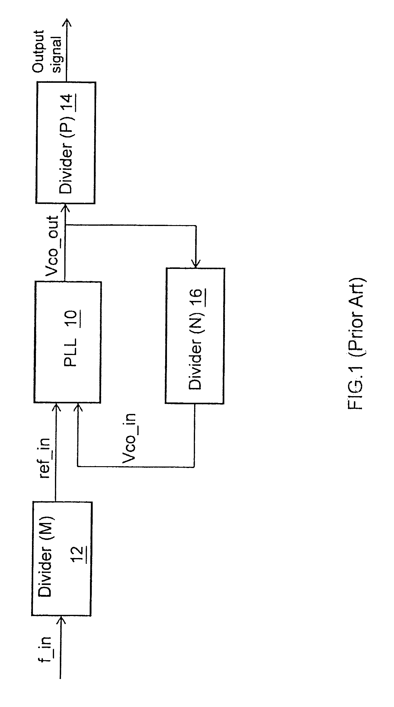
However, the stability of the clocks may be deteriorated by noises and estimated by measuring the jitter outputted from the PLLs. FIG. 1 is a block diagram illustrating a conventional PLL.

Method used


Image

  • Frequency locking structure applied to phase-locked loops
  • Frequency locking structure applied to phase-locked loops
  • Frequency locking structure applied to phase-locked loops

Examples


Embodiment Construction

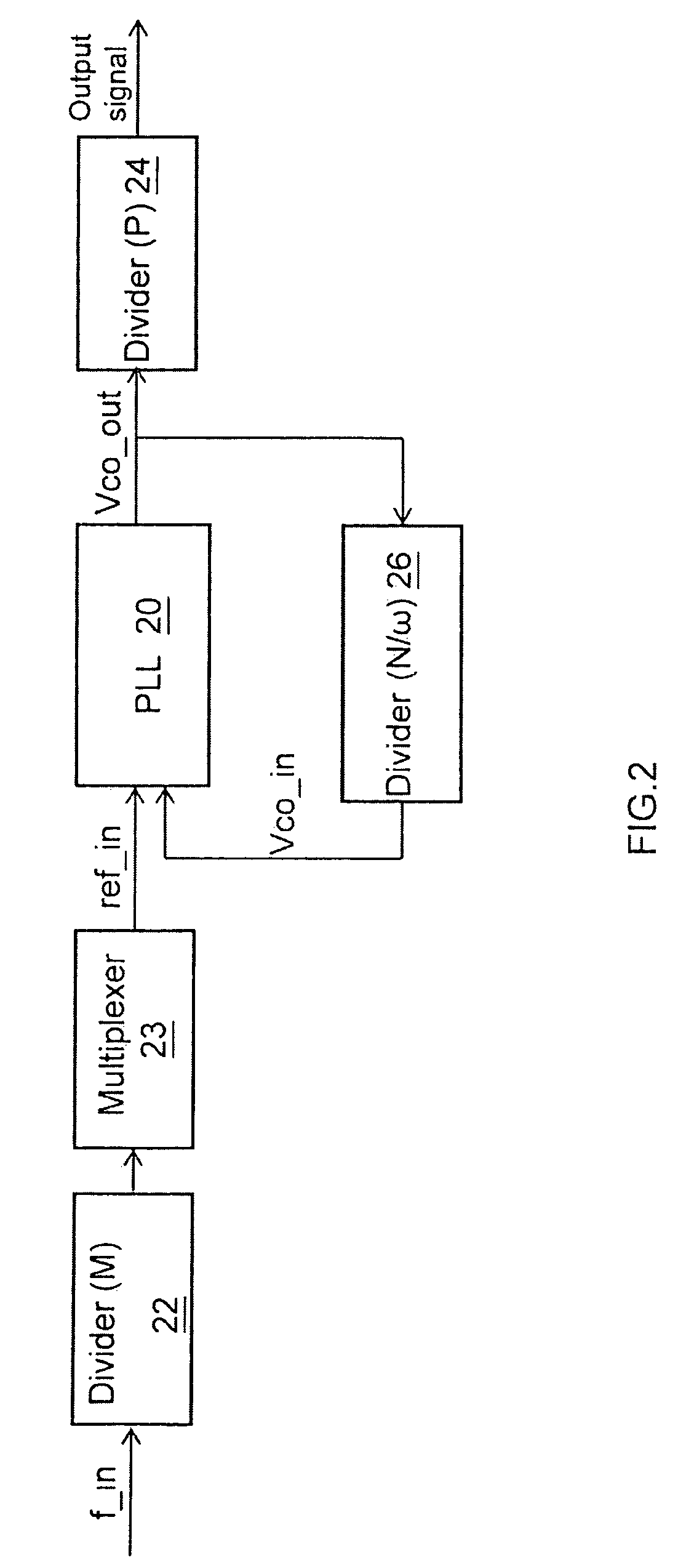
[0017]The invention is directed to a frequency locking structure applied to phase-locked loops. The difference between a reference input signal (ref_in) and an oscillator output signal (Vco_out) is reduced by utilizing a common factor to prevent the oscillator output signal (Vco_out) from clock jitter.

[0018]FIG. 2 is a schematic block diagram illustrating an example frequency locking structure in accordance with one embodiment of the invention. A first divider 22 receives an input signal (f_in) and divides the input signal (f_in) by a first constant factor (M). A multiplexer 23 couples the first divider 22 to receive a signal from the first divider 22 and multiplies the signal from the first divider 22 together with a common factor (ω) to output a reference input signal (ref_in). A phase-locked loop 20 couples the multiplexer 23, receives the reference input signal (ref_in) and a feedback signal (Vco_in) to output an oscillator output signal (Vco_out). A second divider 26 couples th...


PUM


Abstract

A frequency locking structure applied to phase-locked loops (PLL) utilizes a common factor to reduce the difference between an output signal of oscillation and an input signal of reference for the jitter reduction of the input signal of reference. Moreover, a count value of clock signal is an input of a greatest-common-factor calculator to acquire an adaptive value and a feedback adaptive value for the common factor of a divider. Such a frequency locking structure both prevents the PLL from being in error about outputting frequency and dynamically adjusts the common factors for different purposes.

Description

BACKGROUND OF THE INVENTION[0001]1. Field of the Invention[0002]The present invention relates to a frequency locking structure, and more particularly to a frequency locking structure applied to phase-locked loops.[0003]2. Background of the Related Art[0004]Phase-locked loops (PLL) are generally used in the recovery of data and clock, modulation and demodulation of frequency and phase, and generation of stable and multiple clock. For the design of signal-mixing integrated circuits and system-on-chip (SOC), the phase-locked loops are necessary for the variable application requirement. Generally, there are specifications to be tested for the PLLs: lock-in range, lock-in time, and jitter.[0005]The PLLs are capable of generating clean and stable clocks. However, the stability of the clocks may be deteriorated by noises and estimated by measuring the jitter outputted from the PLLs. FIG. 1 is a block diagram illustrating a conventional PLL. An input signal (f_in) is processed by a divider ...

Claims


Application Information

Patent Timeline
Patent Type & Authority Patents(United States)
IPC IPC(8): H03L7/18
CPCH03L7/183H03L7/10
Inventor WANG, JYH-HWANGHUANG, WANG-TIAO
Owner MEGAWIN TECH
Learn More