
Hybrid pressure vessel with separable jacket

a pressure vessel and hybrid technology, applied in the direction of liquid handling, container discharge methods, nuclear elements, etc., can solve the problems of increasing the cost of the tank, significant increase in the size and/or weight of the pressure vessel, etc., and achieve the effect of facilitating heat transfer

Active Publication Date: 2010-04-20
AMTROL LICENSING INC
View PDF35 Cites 33 Cited by
  • Summary
  • Abstract
  • Description
  • Claims
  • Application Information

AI Technical Summary

Benefits of technology

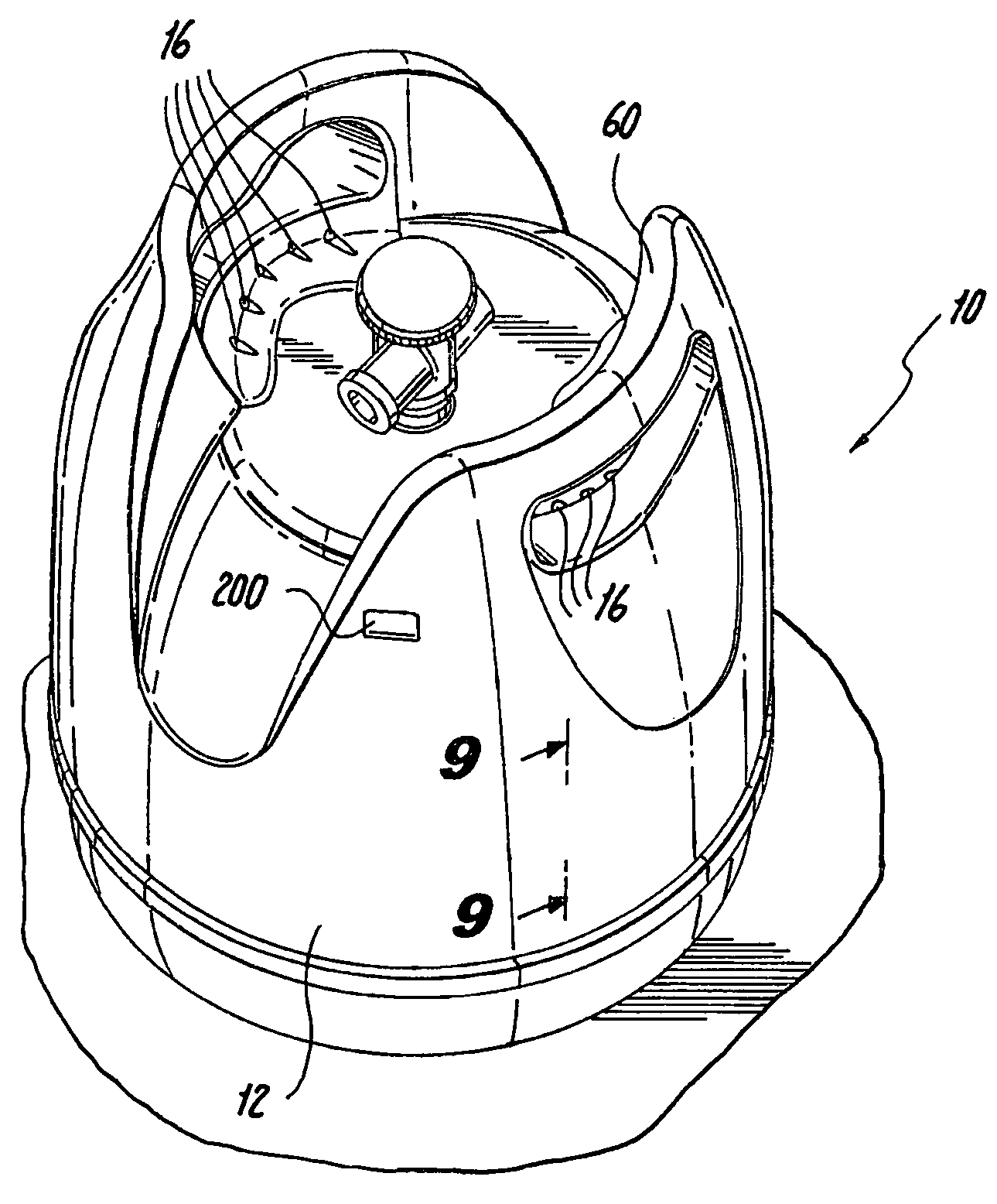
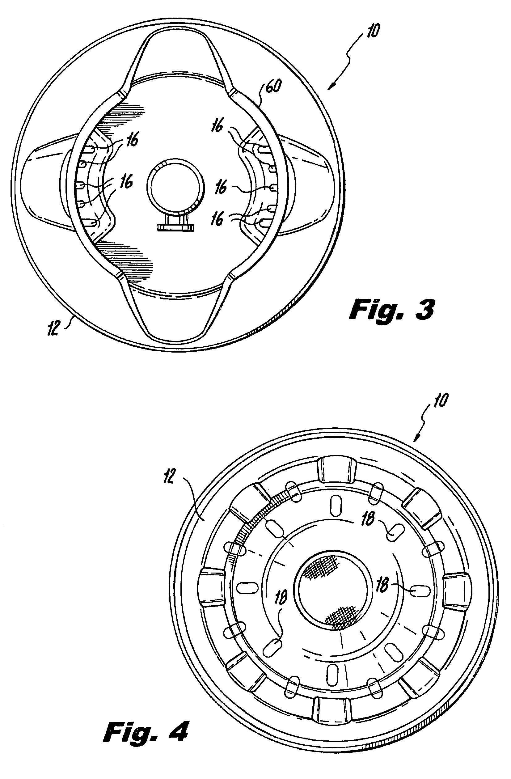
The present invention provides a pressure vessel that includes a hybrid tank formed by a tank liner and an outer reinforcing layer disposed on the tank liner, with the outer reinforcing layer defining at least a portion of an outer surface of the hybrid tank. A protective jacket is disposed thereon and includes an upper support rim and a lower support rim with a cylindrical wall connecting them. The protective jacket is separable into at least two sections. The tank liner may have a higher modulus of elasticity and a lower elastic strain limit than the outer reinforcing layer. The outer reinforcing layer can be fabricated of a thermoplastic material, preferably polypropylene, commingled with glass fibers. The hybrid tank includes an outer anti-corrosion coating and an outer gel coating. The protective jacket can be stacked with other pressure vessels when stacking multiple pressure vessels. The method of manufacturing the pressure vessel includes forming a tank liner, heating glass filaments, commingling the filaments with a thermoplastic material and winding the thermoplastic material and commingled filaments onto the tank liner under application of heat to form a hybrid tank having an outer surface. The method further includes attaching a protective jacket to the hybrid tank, where the protective jacket includes an upper support rim and a lower support rim with a cylindrical wall connecting them. The protective jacket defines a flow channel in fluid communication with the openings and allows for convective heat transfer between the hybrid tank and the environment in which the pressure vessel is situated.

Problems solved by technology

However, this can result in a significant increase in the size and / or weight of the pressure vessel, which can increase the cost of the tank arising from increased material costs and costs associated with transporting the heavier pressure vessels.

Method used


Image

  • Hybrid pressure vessel with separable jacket
  • Hybrid pressure vessel with separable jacket
  • Hybrid pressure vessel with separable jacket

Examples


Embodiment Construction

[0028]Reference will now be made in detail to the present preferred embodiments of the invention, examples of which are illustrated in the accompanying drawings. The method and corresponding steps of the invention will also be described in conjunction with the detailed description of the system.

[0029]The pressure vessels presented herein, and the products of the methods presented herein, may be used for storing pressurized fluids. The present invention is particularly suited for storing and dispensing pressurized fluids while facilitating stacking and portability of the pressure vessel. A pressure vessel constructed in accordance with the present invention is suitable for applications including, but not limited to, storing propane, refrigerant gas, and liquids or gases at low or high pressure.

[0030]In accordance with the invention, a pressure vessel is provided including a hybrid tank having an inner liner and an outer reinforcing layer, and a protective jacket adapted to surround t...


PUM

PropertyMeasurementUnit
modulus of elasticityaaaaaaaaaa
elastic strainaaaaaaaaaa
pressureaaaaaaaaaa

Abstract

A pressure vessel is provided including an inner tank formed from a tank liner surrounded by a wound layer of composite filaments. A protective jacket is disposed on the inner tank that facilitates stacking and portability of the pressure vessel and helps to define an air passage for convective heat transfer between the hybrid tank and the environment.

Description

CROSS-REFERENCE TO RELATED APPLICATIONS[0001]This application claims the benefit of priority from U.S. patent application Ser. No. 29 / 259,834, filed May 16, 2006 and U.S. patent application Ser. No. 11 / 115,992, filed Apr. 25, 2005, which claims priority from U.S. Provisional Patent Application Ser. No. 60 / 564,776, filed Apr. 23, 2004, the disclosures of which are incorporated by reference herein in their entireties.BACKGROUND OF THE INVENTION[0002]1. Field of the Invention[0003]The subject invention is directed to pressure vessels, and more particularly to a pressure vessel having a hybrid tank formed of a tank liner and outer composite layer with a protective jacket disposed thereon.[0004]2. Background of the Related Art[0005]Pressure vessels come in all sizes and shapes, and are made from a variety of materials. The need for lightweight pressure vessels has existed and still exists. There have been many attempts to make light weight pressure vessels that are able to store fluids u...

Claims


Application Information

Patent Timeline
Patent Type & Authority Patents(United States)
IPC IPC(8): F17C1/02G21C9/00
CPCF17C13/00Y10T29/4998F17C2205/0169F17C2205/0196F17C2209/2163F17C2201/058F17C2201/0109F17C2201/032F17C2203/0604F17C2203/0607F17C2203/0643F17C2203/0646F17C2203/0656F17C2203/0673F17C2205/0126F17C2205/0165F17C2205/0176F17C2205/018F17C2205/0308F17C2205/0329F17C2205/054F17C2205/057F17C2205/058F17C2209/221F17C2209/225F17C2221/035F17C2221/038F17C2223/0153F17C2223/033F17C2223/035F17C2223/036F17C2227/0311F17C2227/0383F17C2260/032F17C2260/053F17C2270/0745F17C2205/0115F17C1/06F17C1/10F17C13/003F17C13/084F17C2203/0619F17C2203/0621F17C2203/0624F17C2203/066F17C2203/0663Y02E60/32F17C1/02
Inventor OLIVEIRA, TIAGOGUIMARAES, JOAO CARLOS V. ANTUNESALVES, EDUARDO J.
Owner AMTROL LICENSING INC
Learn More