
Systems and methods for utilizing pulsed radio frequencies in a ring laser gyroscope

a laser gyroscope and pulse radio technology, applied in the field of ring laser gyroscopes, can solve the problems of shortening the laser lifetime and hence gyro reliability and performance, affecting the reliability and performance and reducing the reliability of rlgs which employ interfacial seals. the effect of reducing the number of gyroscopes

Active Publication Date: 2010-04-13
HONEYWELL INT INC
View PDF8 Cites 3 Cited by
  • Summary
  • Abstract
  • Description
  • Claims
  • Application Information

AI Technical Summary

Benefits of technology

The patent describes a ring laser gyroscope that uses a pulsed RF signal to excite a gain medium within a discharge bore. This results in a high-quality optical signal that can be used to measure rotation. The technical effects of this invention include improved accuracy and stability of the optical signal, as well as simplified design and operation.

Problems solved by technology

The integrity of such interfacial seals has historically limited the temperature range, reliability, and lifetime of RLGs which employ the interfacial seals.
This sputtering contaminates the gain medium which results in shortening the laser lifetime and hence gyro reliability and performance.
Additionally, the cathode or cathodes, depending upon the RLG configuration, pump gases from the gain medium producing undesirable gas mix changes.
However, dynamic impedance characteristics of the gain medium within the discharge bore can cause problems related to controlling an amount of power delivered to the gain medium when utilizing such continuous wave (CW) RF signals.

Method used


Image

  • Systems and methods for utilizing pulsed radio frequencies in a ring laser gyroscope
  • Systems and methods for utilizing pulsed radio frequencies in a ring laser gyroscope
  • Systems and methods for utilizing pulsed radio frequencies in a ring laser gyroscope

Examples


Embodiment Construction

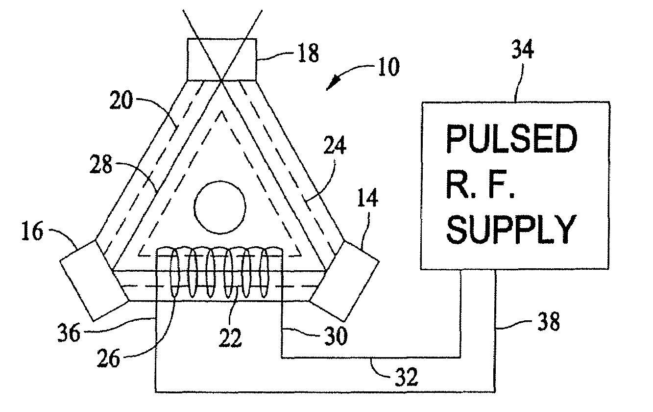
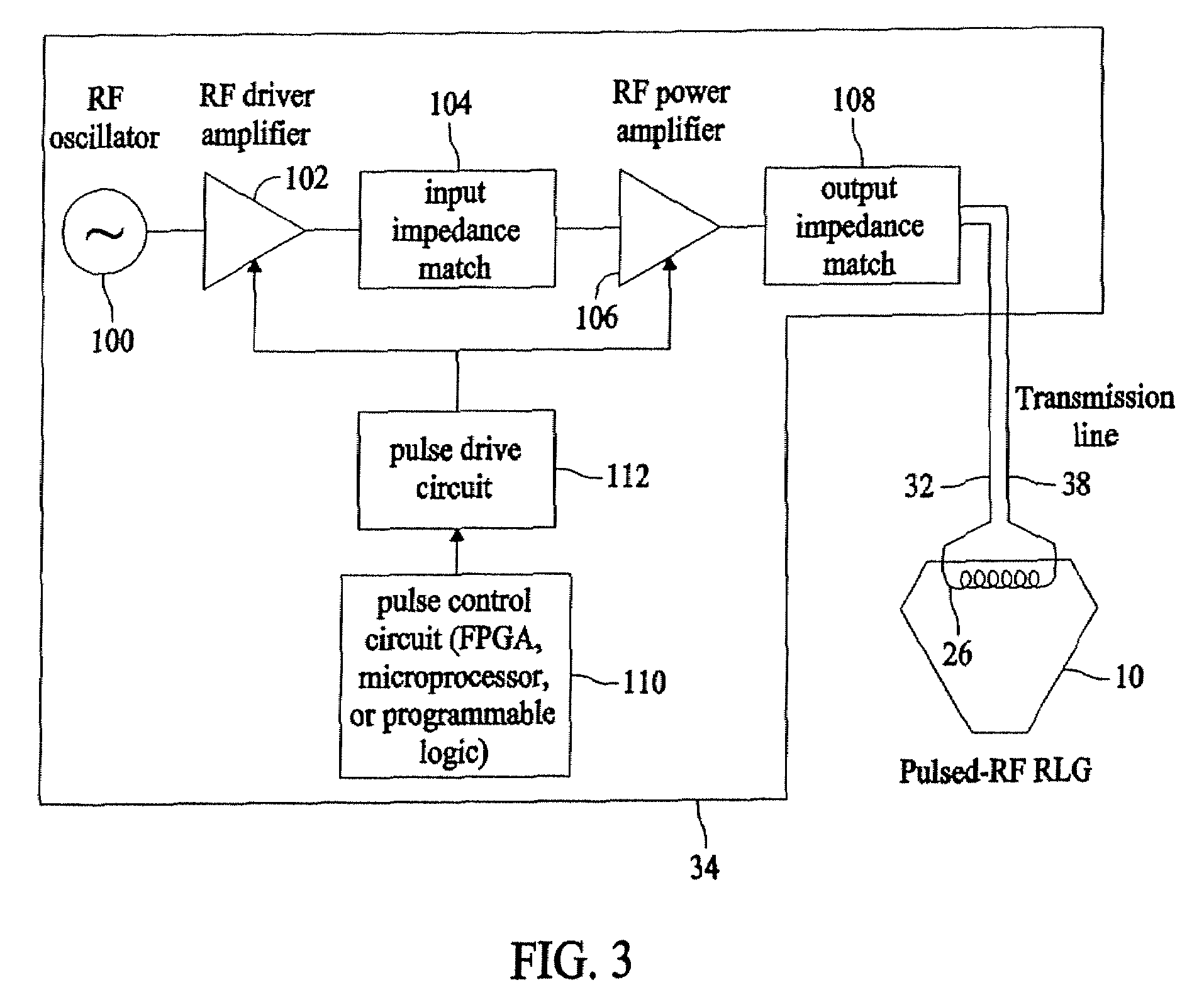
[0018]FIG. 1 is a top view of one embodiment of a ring laser gyroscope (RLG) 10 in which a pulsed radio frequency (RF) is applied to a gain medium. Utilization of pulsed RF reduces average RF power provided to RLG 10 as compared to RLGs which utilize a continuous wave RF signal to initiate and maintain a laser beam within RLG 10. RLG 10 comprises a gyroscope block 12, transducer mirrors 14, 16, a readout mirror 18, discharge bores 20, 22 and 24, and an inductive coil 26. Inductive coil 26 is one embodiment of an RF transmitting device as further described below. Gyroscope block 12, in alternative embodiments, is fabricated from one or more of Zerodur.RTM. (Zerodur is a registered trademark of SCHOTT AG), silica, or another comparable material having stable temperature expansion characteristics. Transducer mirrors 14, 16 and readout mirror 18 are bonded to corners of gyroscope block 12 to form a gas tight seal. A gain medium, for example, helium neon (HeNe) gas may be employed within...


PUM


Abstract

Ring laser gyroscope that includes a gyroscope block, a radio frequency transmitting device, and a radio frequency energy source. The gyroscope block has at least one discharge bore containing a gain medium, and the radio frequency transmitting device is located within the gyroscope block in proximity to at least one discharge bore and located so as to encompass the discharge bore. The radio frequency energy source is configured to apply a pulsed radio frequency signal to the transmitting device.

Description

PRIORITY CLAIM[0001]This application is a CIP of U.S. patent application Ser. No. 11 / 040,469 filed Jan. 21, 2005.BACKGROUND OF THE INVENTION[0002]This invention relates generally to ring laser gyroscopes, and more specifically, to systems and methods for utilizing pulsed radio frequencies within ring laser gyroscopes.[0003]At least some known ring laser gyroscopes (RLGs) utilize a direct current (D.C.) voltage discharge in order to start and maintain laser beams within a discharge cavity located in a block of the RLG. A discharge cavity is also sometimes referred to as a gain bore or discharge bore. In such a utilization, D.C. electrodes must be in direct contact with a gain medium of the laser that is contained within the discharge bore. In order to prevent external materials from leaking around these D.C. electrodes, an interfacial seal is used to bond the electrodes to the laser block. The integrity of such interfacial seals has historically limited the temperature range, reliabi...

Claims


Application Information

Patent Timeline
Patent Type & Authority Patents(United States)
IPC IPC(8): H01S3/083G01C19/64
CPCG01C19/66H01S3/0835H01S3/0975
Inventor BACKES, GLEN B.THORLAND, RODNEY H.
Owner HONEYWELL INT INC
Learn More