
Structure and method for a fast recovery rectifier structure

a rectifier and structure technology, applied in the direction of diodes, semiconductor devices, electrical apparatus, etc., can solve the problems of low efficiency power supply operation, low efficiency, and significant increase in the turn-on loss of the switch, so as to reduce the reverse recovery charge and fast recovery rectifier structure, the effect of maintaining a soft recovery characteristi

Active Publication Date: 2010-04-13
POWER INTEGRATIONS INC
View PDF39 Cites 24 Cited by
  • Summary
  • Abstract
  • Description
  • Claims
  • Application Information

AI Technical Summary

Benefits of technology

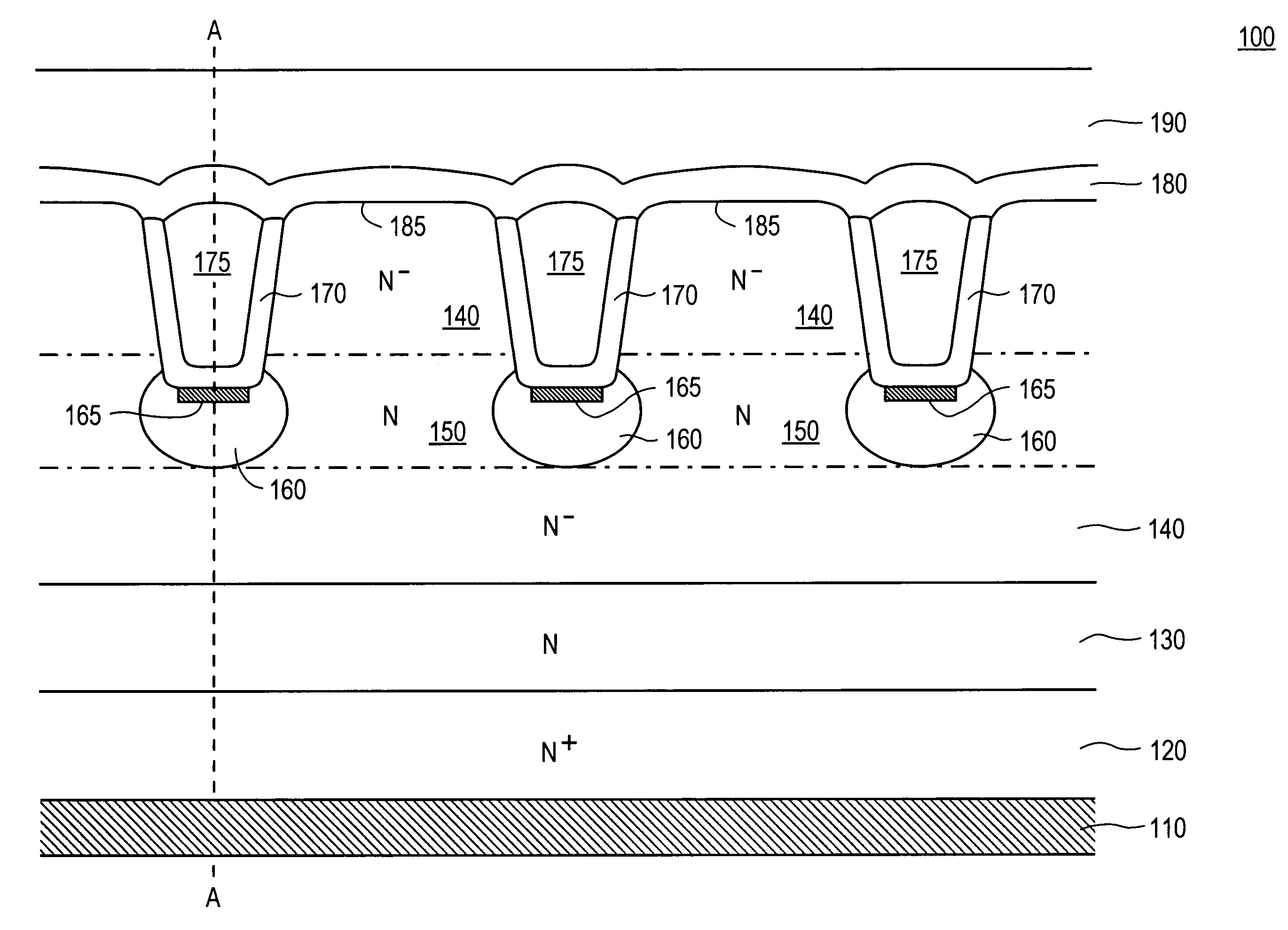
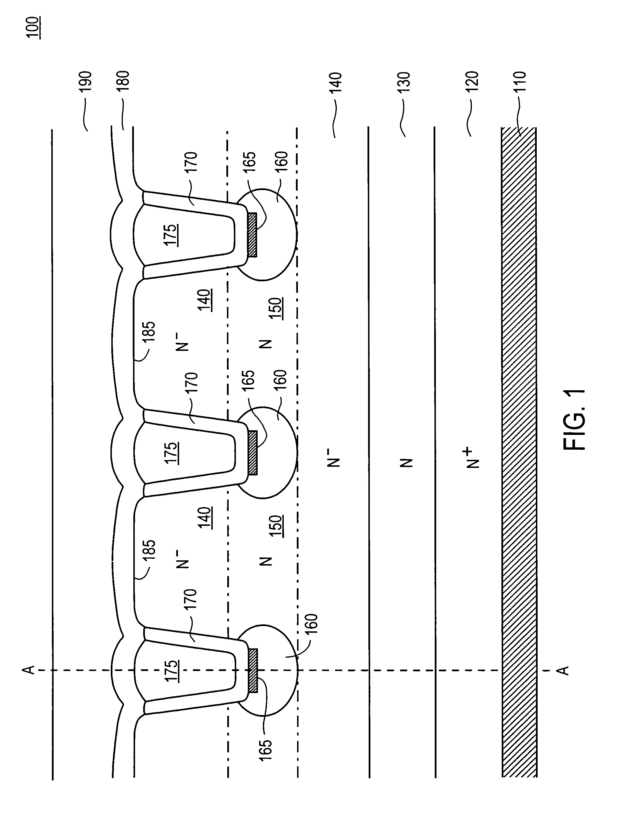
[0010]Accordingly, various embodiments of the present invention disclose an apparatus and method for a fast recovery rectifier structure. Embodiments of the present invention are able to reduce the reverse recovery charge while maintaining a soft recovery characteristic. Also, embodiments of the present invention disclose a silicon based fast recovery rectifier structure involving the creation of Schottky diode regions in series with JFET channel regions, or a merged PiN Schottky (MPS) diode structure. The MPS diode structure enables a higher Schottky to PiN ratio because of smaller geometries, and reduced channel resistance due to N doping between the well regions that reduce the contribution of hole injection during forward conduction, for example in one embodiment.

Problems solved by technology

For example, a reverse recovery current transient appears as an additional component of current during the turn-on of the switch, with the result that the turn-on loss of the switch is significantly higher that it would otherwise be without such reverse recovery component.
Unfortunately, however, if the reverse recovery is too abrupt, then the current and voltage will experience undesirable oscillations.
Such oscillations can result in, for example, low efficiency power supply operation, a deleteriously noisy output (e.g., power supply ripple and / or electromagnetic interference), and / or extremely high and possibly damaging voltage spikes.

Method used


Image

  • Structure and method for a fast recovery rectifier structure
  • Structure and method for a fast recovery rectifier structure
  • Structure and method for a fast recovery rectifier structure

Examples


Embodiment Construction

[0018]Reference will now be made in detail to the preferred embodiments of the present invention, a fast recovery rectifier structure and a method for fabricating the structure, examples of which are illustrated in the accompanying drawings. While the invention will be described in conjunction with the preferred embodiments, it will be understood that they are not intended to limit the invention to these embodiments. On the contrary, the invention is intended to cover alternatives, modifications and equivalents, which may be included within the spirit and scope of the invention as defined by the appended claims.

[0019]Furthermore, in the following detailed description of the present invention, numerous specific details are set forth in order to provide a thorough understanding of the present invention. However, it will be recognized by one of ordinary skill in the art that the present invention may be practiced without these specific details. In other instances, well known methods, p...


PUM


Abstract

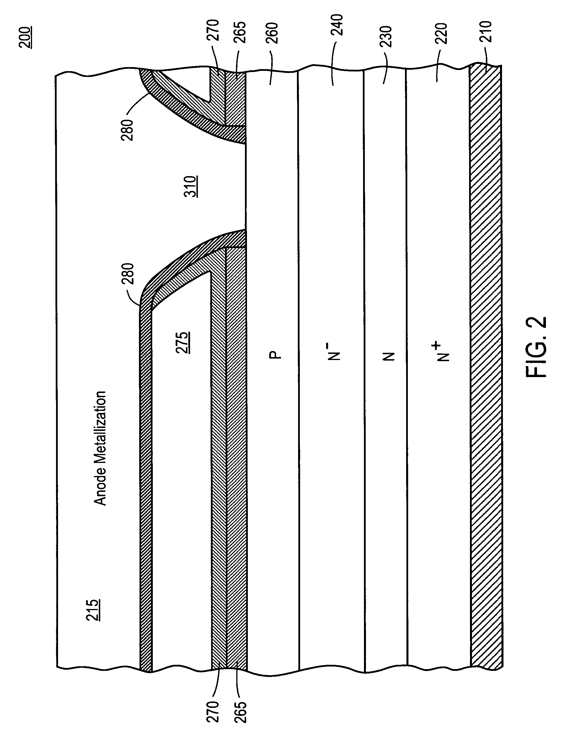
An apparatus and method for a fast recovery rectifier structure. Specifically, the structure includes a substrate of a first dopant. A first epitaxial layer lightly doped with the first dopant is coupled to the substrate. A first metallization layer is coupled to the first epitaxial layer. A plurality of trenches is recessed into the first epitaxial layer, each of which is coupled to the metallization layer. The device also includes a plurality of wells each doped with a second dopant type, wherein each well is formed beneath and adjacent to a corresponding trench. A plurality of oxide layers is formed on walls and a bottom of a corresponding trench. A plurality of channel regions doped with the first dopant is formed within the first epitaxial layer between two corresponding wells. Each of the plurality of channel regions is more highly doped with the first dopant than the first epitaxial layer.

Description

CROSS REFERENCE TO RELATED APPLICATIONS[0001]This application claims priority to the provisional patent application, Ser. No. 60 / 754,550, entitled “Fast Recovery Rectifier Structure,” filed Dec. 27, 2005, and assigned to the assignee of the present invention, which is herein incorporated by reference in its entirety.[0002]This application is related to co-pending, commonly owned U.S. patent application, Ser. No. 10 / 869,718, entitled “Schottky Barrier Rectifier and Method of Manufacturing the Same,” filed Jun. 15, 2004, which is hereby incorporated by reference herein in its entirety.[0003]This application is related to co-pending, commonly owned U.S. patent application, Ser. No. 11 / 320,313, entitled “Ultrafast Recovery Diode,” filed Dec. 27, 2005, which is hereby incorporated by reference herein in its entirety.BACKGROUND OF THE INVENTION[0004]1. Field of the Invention[0005]Embodiments of the present invention relate to the field of rectifiers. More particularly, embodiments of the ...

Claims


Application Information

Patent Timeline
Patent Type & Authority Patents(United States)
IPC IPC(8): H01L29/80
CPCH01L27/0641H01L27/0814H01L27/0817H01L29/0623H01L29/8725H01L29/8083H01L29/861H01L29/872H01L29/7722
Inventor FRANCIS, RICHARDFAN, YANG YUJOHNSON, ERICHOANG, HY
Owner POWER INTEGRATIONS INC
Learn More