
Rock breaking machine and lubricating method

a technology of lubricating method and rock breaking machine, which is applied in the field of rock breaking machine, can solve the problems of difficult to feed lubricant from a remote lubricating container into the bearing members, the lubricating device is prone to impacts and impurities, and the tool of the rock breaking machine and its bearings are subject to heavy stress, so as to reduce the need for service, the lubricating device is closer to the lubricating object and the lub

Inactive Publication Date: 2010-04-13
SANDVIK MINING & CONSTR OY
View PDF33 Cites 14 Cited by
  • Summary
  • Abstract
  • Description
  • Claims
  • Application Information

AI Technical Summary

Benefits of technology

[0008]An advantage of the invention is that lubricant in the lubricant container arranged in the body warms up according to the operating temperature of the rock breaking machine, thus allowing effective lubrication in cold conditions, too. Warm lubricant flows easier than cold and stiff lubricant. The transfer of lubricant from the lubricant container according to the invention to the object to be lubricated poses no problems. Since the solution according to the invention ensures sufficient lubrication of the tool of the rock breaking machine in all conditions, the operating life of the tool and rock breaking machine may be longer and the need for service less frequent. A further advantage is that the dividing member keeps the lubricant and the pressure medium separate from each other, in which case no lubricant is allowed into the pressure medium system nor any pressure medium into the lubricating system. This ensures functioning of the lubricating system and pressure medium system.
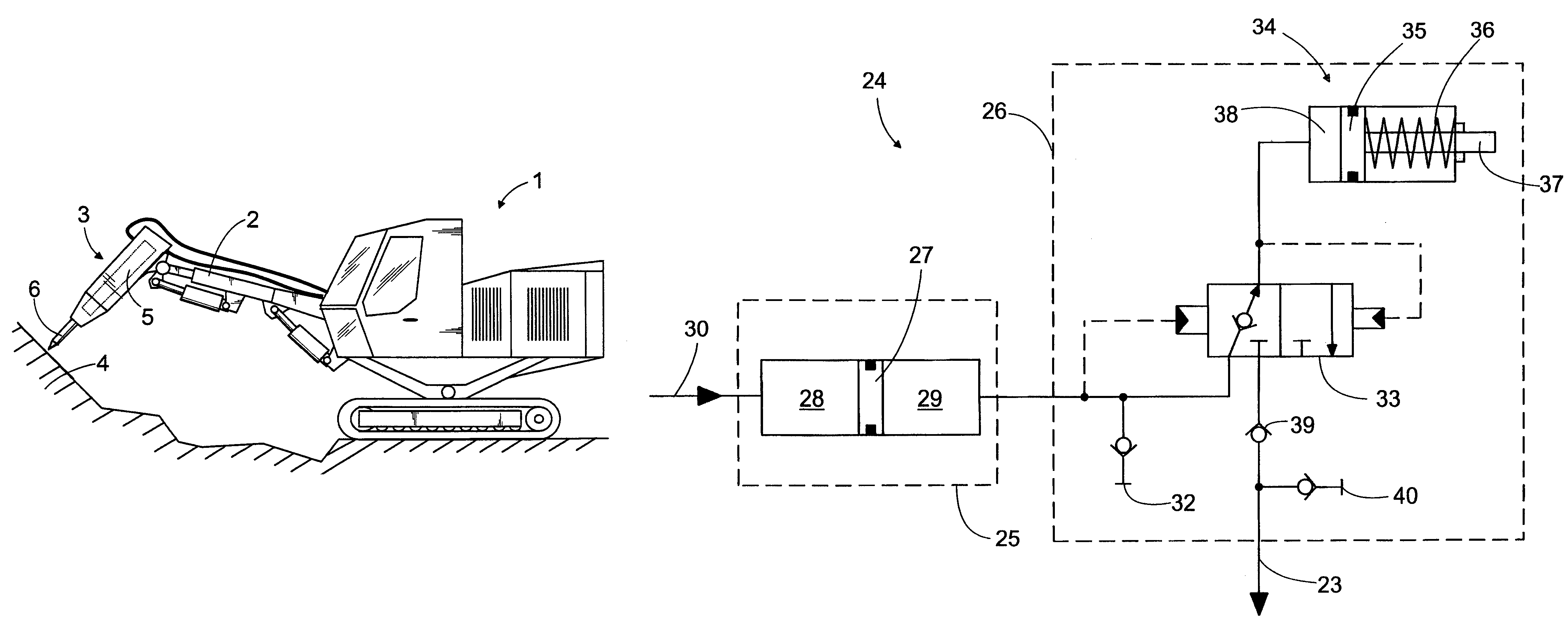
[0009]The basic idea of an embodiment according to the invention is that in addition to the lubricant container, the lubricant channel and lubricating device included in the lubricating system are integrated into the body of the rock breaking machine. In that case, the distance from the lubricant container to the lubricating device and further to the object to be lubricated may be short. A further advantage is that the whole lubricating system is covered by the body of the rock breaking machine. The temperature of the lubricant in the lubricant container, transfer device and lubricant channel may further substantially correspond to the operating temperature of the rock breaking machine. Neither does this embodiment require any lubricant hoses, which makes the structure more durable and the need for service less frequent.
[0011]The basic idea of an embodiment according to the invention is that the lubricant container is a cylindrical space which is formed in the body of the rock breaking machine and is divided into a pressure space and a lubricant space by a dividing member. The dividing member is a piston, which is sealed against the cylinder surfaces of the lubricant container. The piston is arranged to move freely in the longitudinal direction of the lubricant container, depending on the pressure difference between the pressures acting in the pressure space and lubricant space. The forming of such a cylindrical space in the body of the rock breaking machine is relatively simple.

Problems solved by technology

The tool of the rock breaking machine and its bearings are subjected to heavy stress during use.
In that case, the lubricating device is prone to impacts and impurities during use.
A further problem that has been noted is that it is difficult to feed lubricant from a remote lubricant container into the bearing members.
In cold conditions, in particular, lubrication may be insufficient since the lubricant is cold and stiff in the lubricant container arranged on the outer surface of the rock breaking machine.

Method used


Image

  • Rock breaking machine and lubricating method
  • Rock breaking machine and lubricating method
  • Rock breaking machine and lubricating method

Examples


Embodiment Construction

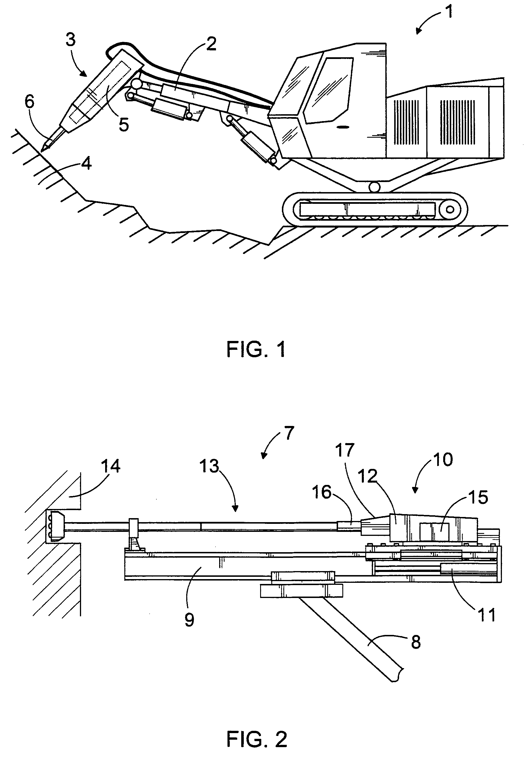
[0024]In FIG. 1, an impact hammer 3 is arranged in a boom 2 of an excavator 1. The impact hammer 3 can be pressed against the material 4 to be broken by means of the boom 2 while a percussion device 5 provided in the impact hammer 3 provides impact pulses for a tool 6 connected to the impact hammer 3. The tool 6 transmits the impact pulses to the material 4 that is being operated on, such as rock, concrete or another hard material, and makes it break. The impact hammer 3 may be arranged in any movable basic machine or, for example, in a drilling boom mounted in a fixed base. The impact hammer 3 may be operated by pressure medium, in which case it may be connected to the hydraulic system of an excavator 1 or the like. On the other hand, the percussion device 5 of the impact hammer 3 may be electrically operated or in any other way.

[0025]FIG. 2 illustrates a rock drilling unit 7, which may be arranged in a drill boom 8 of a rock drilling rig. The rock drilling unit 7 may comprise a fe...


PUM

PropertyMeasurementUnit
volumeaaaaaaaaaa
pressureaaaaaaaaaa
volumesaaaaaaaaaa

Abstract

A rock breaking machine and to a method of lubricating a tool of a rock breaking machine. The lubricating system comprises at least one lubricant channel (23) into which lubricant is fed by a lubricating device (24). Lubricant is supplied to the bearing members (19) of the tool (6, 13) of the rock breaking machine. The lubricating device comprises a lubricant container (25) and a transfer device (26). The transfer device (26) controls the feed of lubricant into the lubricant channel. The lubricant container (25) is integrated into the body (17, 18) of the rock breaking machine.

Description

BACKGROUND OF THE INVENTION[0001]The invention relates to a rock breaking machine comprising: a body; a percussion device for generating impact pulses in a tool that is connectable to the rock breaking machine, bearing members for supporting the tool onto the rock breaking machine and a lubricating system for lubricating the bearing members. The lubricating system comprises at least one lubricant channel, and at least one lubricating device for feeding lubricant along the lubricant channel to the bearing members of the tool. The lubricating device comprises at least one lubricant container and a transfer device for feeding lubricant, the lubricant container being arranged in the body of the rock breaking machine.[0002]The invention further relates to a method of lubricating a tool of a rock breaking machine.[0003]Rock breaking machines, such as impact hammers and rock drilling machines, comprise a tool which is provided with impact pulses by a percussion device of the rock breaking ...

Claims


Application Information

Patent Timeline
Patent Type & Authority Patents(United States)
IPC IPC(8): B25D17/26B23B45/16B25DE21B1/00
CPCE21B1/00F16N13/02Y10S173/03E21B1/38B25D17/26E02F9/00
Inventor OKSMAN, MIKA
Owner SANDVIK MINING & CONSTR OY
Learn More