Platform link wrist mechanism

a wrist mechanism and platform technology, applied in the field of surgical tools, can solve the problems of denying the surgeon the flexibility of tool placement found, saving millions of hospital days and millions of dollars annually in hospital residency costs, and relating to current mis technology

Active Publication Date: 2010-04-06
INTUITIVE SURGICAL OPERATIONS INC
View PDF16 Cites 2866 Cited by
  • Summary
  • Abstract
  • Description
  • Claims
  • Application Information

AI Technical Summary

Benefits of technology

[0025]In a second aspect of the present invention, the robotic surgical tool includes a tool base disposed near the proximal end of the shaft. The tool base includes mechanisms for actuating the wrist mechanism and often mechanisms for actuating the end effector. Mechanisms for actuating the wrist mechanism includes mechanisms for advancing or retracting the first rod. In some embodiments, such mechanisms comprises a first rotational actuation member to which the first rod is attached so that rotation of the first rotational actuation member advances or retracts the first rod. Typically, another rod is attached to the first rotational actuation member in a position diametrically opposite to the first rod so that rotation of the first rotational actuation member simultaneously advances the first rod and retracts the diametrically opposite rod. In some embodiments, the tool base further comprises a second rotational actuation member to which the second rod is attached so that rotation of the second rotational actuation member advances or retracts the second rod substantially along the axial direction. Again, another rod is often attached to the second rotational actuation member in a position diametrically opposite to the second rod so that rotation of the second rotational actuation member simultaneously advances the second rod and retracts the diametrically opposite rod. Thus, by rotating the first and second rotational actuation members, the distal member is tipped through two angles, or a compound angle, so that the distal member faces any desired direction. This allows refined control of the end effector throughout three dimensions.
[0026]The robotic surgical tool of the present invention may also include provisions for roll movement. Roll movement is achieved by rotating the shaft around its central axis. Since the shaft is connected to a guide tube through which the plurality of rods pass, rotation of the shaft rotates guide tube which in turn rotates the rods around the central axis which is parallel to the axial direction. To actuate such roll, the above described tool base comprises a roll pulley which rotates the shaft. Since the rods extend through the roll pulley and attach to the rotational actuation members, such rotation is possible by flexing of the rods. Due to the length, thickness and flexibility of the rods, 360 degree rotation is possible. Thus, pitch, yaw and roll movement can be individually actuated by the tool base, particularly by manipulation of the rotational actuation members and roll pulley.
[0028]Such rotation is assisted by flexibility of the rods. Generally, each rod is flexible in at least one direction. For example, when each rod has a rectangular cross-section, having a wide side and a narrow side, the rod may be flexible along the wide side yet rigid along the narrow side. When the rods are arranged so that the wide sides are parallel to the perimeter of the shaft, flexibility along the wide sides allows each rod to bend slightly inward, toward the center of the shaft or the longitudinal axis. This allows greater rotation of the distal member and flexibility in design parameters.

Problems solved by technology

Thus, an increased adoption of minimally invasive techniques could save millions of hospital days and millions of dollars annually in hospital residency costs alone.
There are many disadvantages relating to current MIS technology.
For example, existing MIS instruments deny the surgeon the flexibility of tool placement found in open surgery.
Most current laparoscopic tools have rigid shafts, so that it can be difficult to approach the worksite through the small incision.
Additionally, the length and construction of many endoscopic instruments reduces the surgeon's ability to feel forces exerted by tissues and organs on the end effector of the associated tool.
The lack of dexterity and sensitivity of endoscopic tools is a major impediment to the expansion of minimally invasive surgery.

Method used


Image

  • Platform link wrist mechanism
  • Platform link wrist mechanism
  • Platform link wrist mechanism

Examples


Embodiment Construction

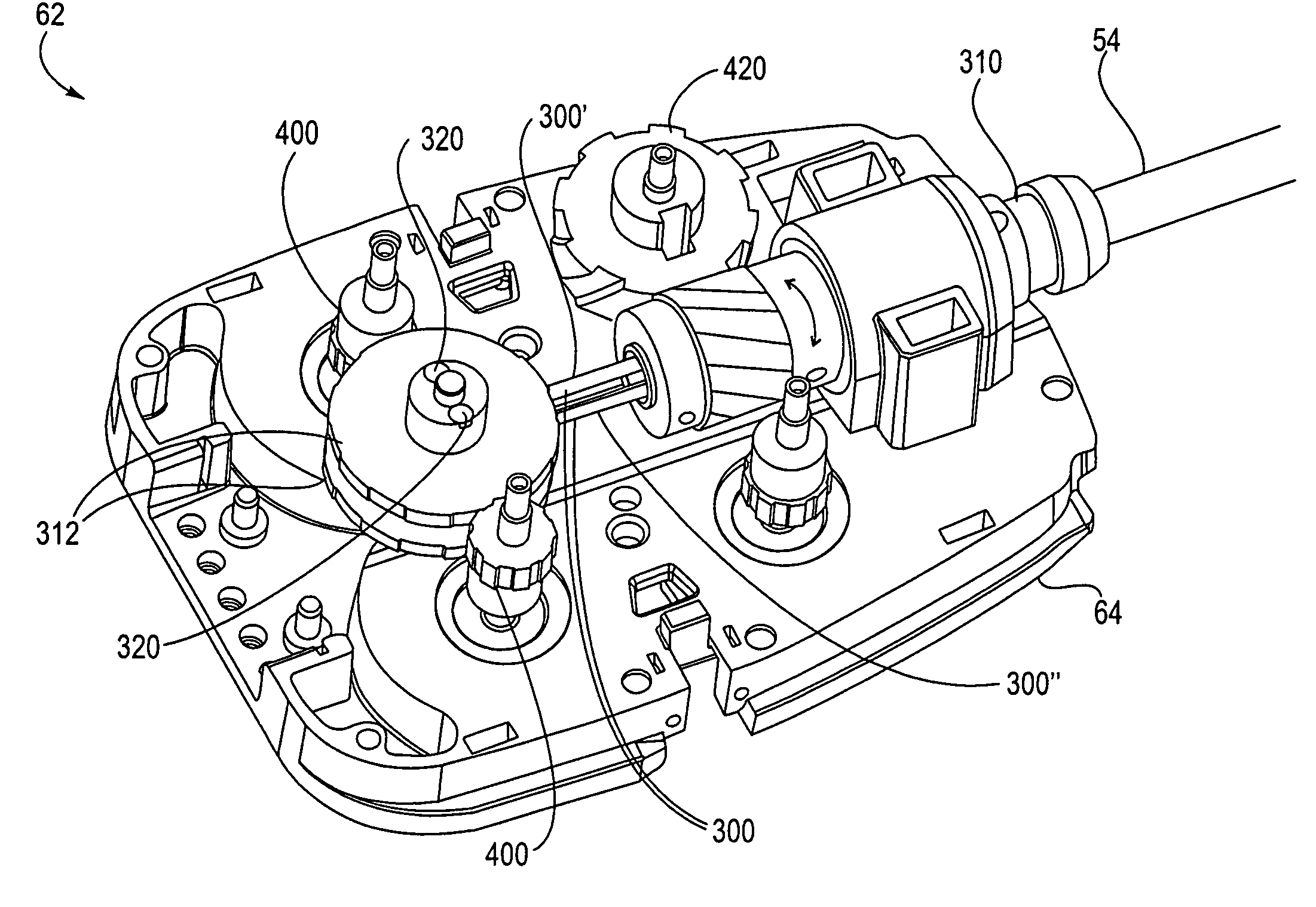
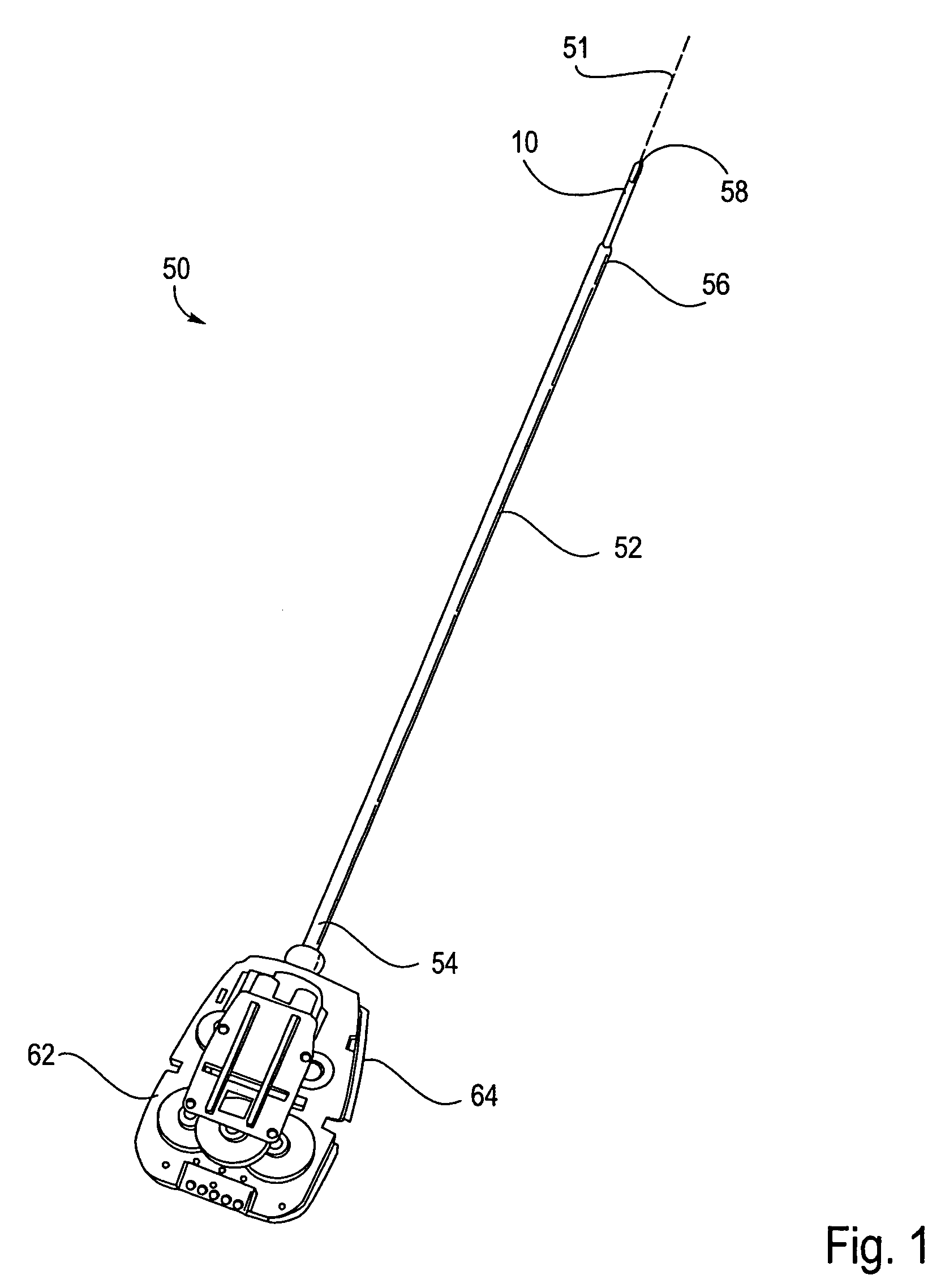
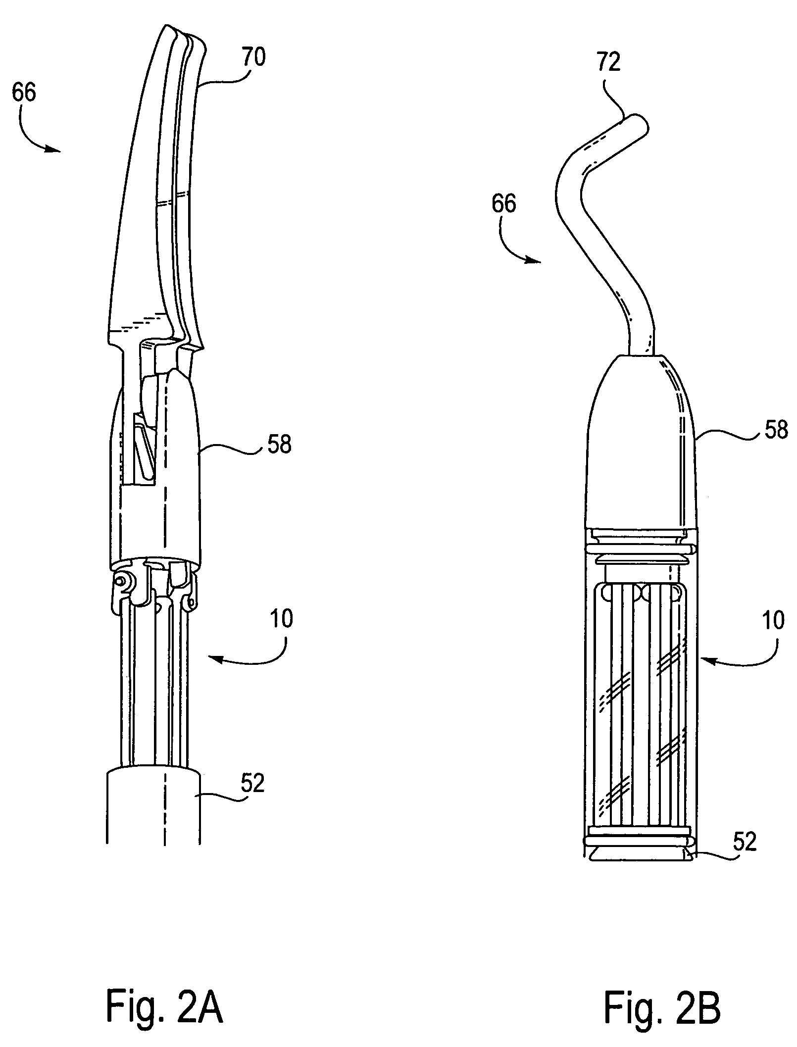
[0061]FIG. 1 illustrates a surgical tool 50 of the present invention which is used in robotic surgery systems. The surgical tool 50 includes a rigid shaft 52 having a proximal end 54, a distal end 56 and a longitudinal axis therebetween. The proximal end 54 is coupled to a tool base 62. The tool base 62 includes an interface 64 which mechanically and electrically couples the tool 50 to a manipulator on the robotic arm cart. A distal member, in this embodiment a distal clevis 58, is coupled to shaft 52 by a wrist joint or wrist mechanism 10, the wrist mechanism 10 providing the distal clevis 58 with at least 1 degree of freedom and ideally providing at least 3 degrees of freedom. The distal clevis 58 supports a surgical end effector 66, the actual working part that is manipulable for effecting a predetermined treatment of a target tissue. Exemplary surgical end effectors 66 are illustrated in FIGS. 2A-2B. Grasping jaws 70 are illustrated in FIG. 2A, while a cautery isolation effector...


PUM


Abstract

The present invention provides a robotic surgical tool for use in a robotic surgical system to perform a surgical operation. The robotic surgical tool includes a wrist mechanism disposed near the distal end of a shaft which connects with an end effector. The wrist mechanism includes a distal member configured to support the end effector, and a plurality of rods extending generally along an axial direction within the shaft and movable generally along this axial direction to adjust the orientation of the distal member with respect to the shaft. Advancement or retraction of a first rod generally along the axial direction tips the base through a first angle. The addition of a second angle allows the distal member to direct the end effector in essentially a compound angle. The robotic surgical tool may also include provisions for roll movement.

Description

CROSS-REFERENCES TO RELATED APPLICATIONS[0001]This application is a continuation of U.S. patent application Ser. No. 10 / 758,050, filed on Jan. 14, 2004, now U.S. Pat. No. 7,066,926, which is a continuation of U.S. patent application Ser. No. 10 / 186,176, filed on Jun. 28, 2002, now U.S. Pat. No. 6,699,235, which was based on and claimed the benefit of U.S. Provisional Patent Application No. 60 / 301,967, filed Jun. 29, 2001, and U.S. Provisional Patent Application No. 60 / 327,702, filed Oct. 5, 2001, the entire disclosures of which are incorporated herein by reference.[0002]This application is related to the following patents and patent applications, the full disclosures of which are incorporated herein by reference:[0003]PCT International Application No. PCT / US98 / 19508, entitled “Robotic Apparatus”, filed on Sep. 18, 1998, and published as WO99 / 50721;[0004]U.S. patent application Ser. No. 09 / 418,726, entitled “Surgical Robotic Tools, Data Architecture, and Use”, filed on Oct. 15, 1999;...

Claims


Application Information

Patent Timeline
Patent Type & Authority Patents(United States)
IPC IPC(8): G05G11/00A61B17/00A61B17/28G05G9/00A61B19/00B25J11/00B25J9/06A61B34/30B25J17/02
CPCA61B19/22A61B17/00234A61B19/2203A61B2017/2929A61B2017/2934A61B2019/2226Y10S606/914A61B2019/2242A61B2019/2249Y10T74/20335Y10T74/20317Y10T74/20305A61B2019/2234A61B34/70A61B34/71A61B34/30A61B2034/304A61B2034/305A61B34/72
Inventor WALLACE, DANIEL T.ANDERSON, S. CHRISTOPHERMANZO, SCOTT
Owner INTUITIVE SURGICAL OPERATIONS INC
Why Eureka
Try Eureka