Processor comprising an integrated debugging interface controlled by the processing unit of the processor

a debugging interface and processor technology, applied in the field of debugging interfaces integrated into processors, can solve problems such as unoptimized solutions

Active Publication Date: 2010-03-30
STMICROELECTRONICS SRL
View PDF4 Cites 0 Cited by
  • Summary
  • Abstract
  • Description
  • Claims
  • Application Information

AI Technical Summary

Benefits of technology

[0010]Another embodiment makes the internal registers of the debugging interface read- and / or write-accessible to the processing unit of the processor, without further loading the access bus for accessing the memory of the processor, and while limiting the number of additional components required.

Problems solved by technology

In terms of number of components implemented, this solution is not optimal either.

Method used


Image

  • Processor comprising an integrated debugging interface controlled by the processing unit of the processor
  • Processor comprising an integrated debugging interface controlled by the processing unit of the processor
  • Processor comprising an integrated debugging interface controlled by the processing unit of the processor

Examples


first embodiment

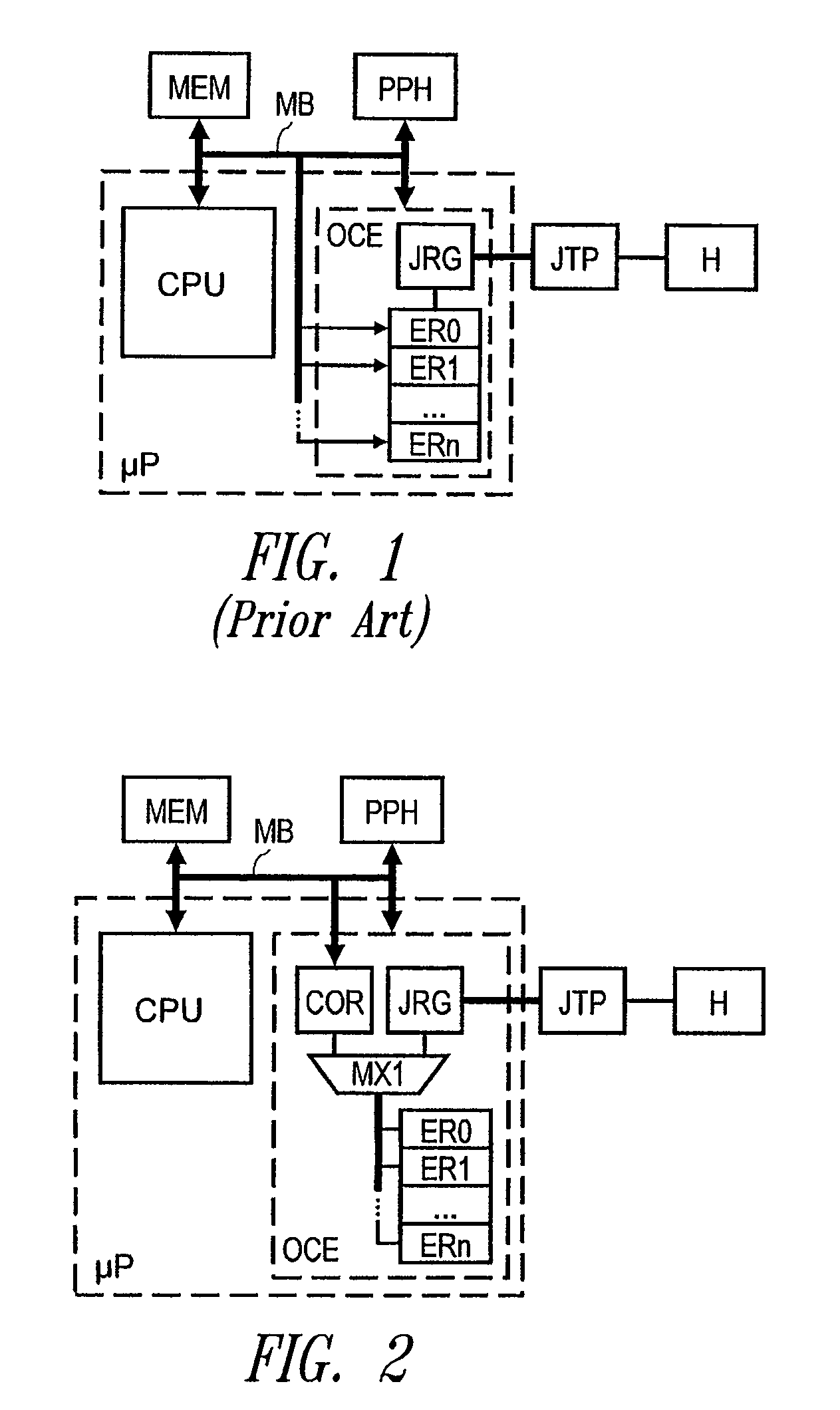
[0039] each of the internal registers ER0-ERn of the interface OCE is linked to a communication register COR of the test interface and to the bus interface unit JRG through a multiplexer MX1. The register COR is accessible directly from the bus MB.

[0040]Thus, the processing unit CPU can supply in the register COR a datum to be written and an address of an internal register ER0-ERn in which the datum must be written. Using this information, the debugging interface can determine the write operation to be performed in an internal register.

[0041]Similarly, the unit CPU can supply in the register COR an address of an internal register ER0-ERn to be read. The debugging interface can then read the register corresponding to the address received and write the datum read in the register COR. The processing unit can then read the register COR to obtain the value read in the internal register corresponding to the address supplied.

[0042]These write and read operations are possible without the in...

second embodiment

[0055]FIG. 4 represents the processor. FIG. 4 is identical to FIG. 2, except that the register COR is not accessible directly from the bus MB but through a multiplexer MX1′, and the register COR is linked to the rest of the circuit without going through a multiplexer such as MX1. Another input of the multiplexer MX1′ is connected to the bus interface unit JRG.

[0056]In the embodiment shown in FIG. 4, the unit CPU can supply in the register COR a datum to be written and an address of an internal register ER0-ERn in which the datum must be written. Using this information, the debugging interface OCE can determine the write operation to be performed in an internal register.

[0057]Similarly, the processing unit CPU can also supply in the register COR an address of an internal register ER0-ERn to be read. The interface OCE can then, in the same way, transfer the content of the register corresponding to the address received into the register COR. The processing unit can then read the regist...


PUM


Abstract

The systems and methods disclosed relate to a processor comprising a processing unit and a debugging that which can be connected to an external emulator for debugging a program executed by the processor, the debugging interface including internal resources at least partially accessible to the external emulator. According to one embodiment, the debugging interface includes a selecting circuit for selecting an internal resource of the debugging interface, according to a reference supplied by the processing unit, and an access circuit that transfers a datum between the resource selected and a data field accessible by the processing unit.

Description

BACKGROUND OF THE INVENTION[0001]1. Field of the Invention[0002]The present invention relates to processors (microprocessors or microcontrollers) and more particularly to a debugging interface integrated into a processor.[0003]2. Description of the Related Art[0004]Such a debugging interface enables an external emulator to be connected to the processing unit of the processor and instructions to be executed to be sent to it. The processor comprises a debugging mode in which the debugging interface is active and provides the processing unit with instructions received from the external emulator. The instructions supplied to the processor by the debugging interface then replace the instructions coming from the program memory.[0005]For this purpose, the debugging interface generally comprises a set of internal data transfer, control and status registers, which are accessible to the external emulator through an external port. The external port conforms, for example, to the standard IEEE 1...

Claims


Application Information

Patent Timeline
Patent Type & Authority Patents(United States)
IPC IPC(8): G06F11/00
CPCG06F11/3656
Inventor AYRIGNAC, RENAUDROBERT, XAVIER
Owner STMICROELECTRONICS SRL
Why Eureka
Try Eureka