Bowling pin setting device

a technology for positioning and repositioning bowling pins, which is applied in the field of bowling pin positioning and/or repositioning devices, can solve the problems of inability to drag the pins into the openings of the positioning template and hence in an orderly manner, the procedure is relatively long, and the cost of energy is not enough, so as to achieve a simple and reliable system of actuation

Active Publication Date: 2018-05-31
GEMAC
View PDF4 Cites 0 Cited by
  • Summary
  • Abstract
  • Description
  • Claims
  • Application Information

AI Technical Summary

Benefits of technology

[0041]In this way, a simple, reliable system for actuating the carriage is provided.

Problems solved by technology

When the pins are knocked down and / or when they are subsequently dragged towards the positioning template, it can occur that some of the cables become entangled with each other, with the consequence that it becomes impossible to drag the pins into the openings of the positioning template and hence to arranged in an orderly manner on the lane.
However, these prior art solutions do not allow to exactly identify which cables are entangled, so that the lifting and releasing procedure is carried out for all pins, including those connected to the cables that are not entangled, the procedure thus being relatively long and needlessly costly from the standpoint of energy.

Method used


Image

  • Bowling pin setting device
  • Bowling pin setting device
  • Bowling pin setting device

Examples


Embodiment Construction

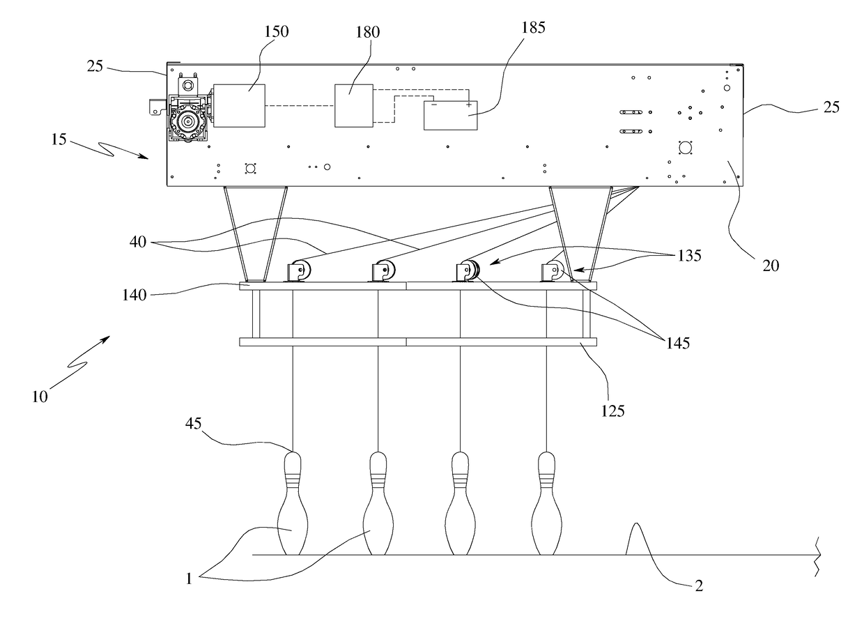
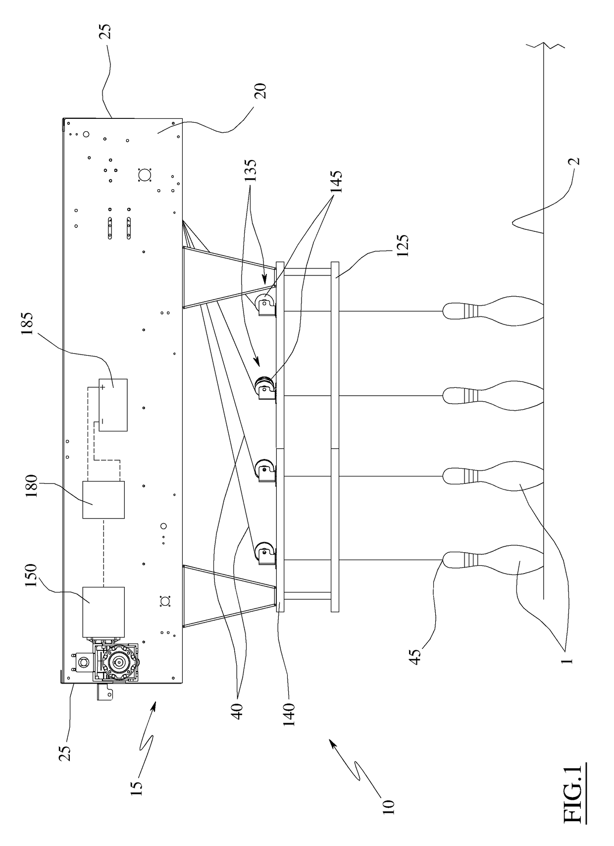
[0048]With particular reference to the figures, the numeral 10 globally indicates a device for positioning pins 1 on a bowling lane 2.

[0049]The positioning device 10 is provided with support frame 15, which comprises a pair of lateral sides 20, having longitudinal axes that are substantially parallel to each other, and a pair of uprights 25, parallel to each other and adapted to connect the ends of a lateral side 20 with the corresponding ends of the other lateral side 20.

[0050]The support frame 15 is positioned above the bowling lane 2, at a distance therefrom that is always greater than the height of a pin 1 positioned vertically, and in such a way that the longitudinal axes of the lateral sides 20 lie on a plane that is substantially parallel to a plane of lay of the lane 2.

[0051]The support frame 15 can for example be sustained in position by means of a structure made of metal or masonry (not shown in the drawings).

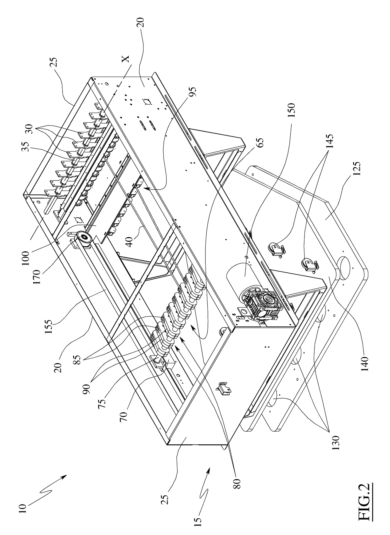
[0052]As shown in FIG. 2, the positioning device 10 comprises a ...


PUM


Abstract

A positioning system for bowling pins includes: a support frame; levers, each independently rotatably associated to the frame, according to an oscillating axis oscillating between rest and perturbed positions; cables, each having first and second ends, fixed to a respective lever; a carriage slidably associated to the support frame; first guides connected to the carriage, each configured to contact a respective cable between the respective lever and pin; a positioning template, provided with accommodating openings of the pins, in which a portion of a corresponding cable is inserted; brakes, each connected to the support frame, associated to a respective cable and actuatable between a blocking position and an unblocking position; an electric motor to actuate the carriage between first and second positions; sensors, each of which is associated to a corresponding lever and is configured the lever position; a control, which detects lever positions and manages the motor and brakes.

Description

TECHNICAL FIELD[0001]The present invention relates to a device for positioning and / or repositioning bowling pins and, more specifically, a device for positioning and / or repositioning bowling pins in which each pin is connected to a respective cable.PRIOR ART[0002]Bowling lanes are known, in which pins are fastened by means of cables to a positioning device whose task is to array the pins on the lane, in the regulation equilateral triangle arrangement, after each throw of the bowling ball.[0003]When the ball is thrown, the positioning device is configured not to act on the cable, so that the pins hit by the ball can be knocked down.[0004]Subsequently, the positioning device pulls the cables, dragging the pins to enter the openings of a positioning template, adapted to distance the pins and arrange them according to the triangle arrangement.[0005]After this operation, the cables are gradually released, setting the pins on the lane.[0006]When the pins are knocked down and / or when they ...

Claims


Application Information

Patent Timeline
Patent Type & Authority Applications(United States)
IPC IPC(8): A63D5/08
CPCA63D5/08A63B2243/0054
Inventor DI DIO, MARIO GIOVANNI
Owner GEMAC
Why Eureka
Try Eureka