Liquid crystal display device

a display device and liquid crystal technology, applied in static indicating devices, instruments, non-linear optics, etc., to achieve the effect of preventing uneven display and tolerating uneven injection amoun

Active Publication Date: 2010-03-30
JAPAN DISPLAY CENTRAL CO LTD
View PDF13 Cites 7 Cited by
  • Summary
  • Abstract
  • Description
  • Claims
  • Application Information

AI Technical Summary

Benefits of technology

[0012]An object of the present invention is to provide a liquid crystal display device configured to prevent unevenness in display attributable to a difference in a cell gap between a display region and a peripheral region while tolerating unevenness in an amount of injection of liquid crystal.
[0014]According to the present invention, the clearance between the substrates is gradually widened outward in the peripheral region. In this way, the cell gap is gently changed from the display region to the peripheral region. Accordingly, it is possible to prevent unevenness in display attributable to a difference in the cell gap between the display region and the peripheral region. Moreover, if the amount of injection of the liquid crystal is excessive, the excessive liquid crystal is filled in a zone of the peripheral region where the clearance is widened. As a result, it is possible to tolerate unevenness in the amount of injection of the liquid crystal.

Problems solved by technology

Moreover, if the amount of injection of the liquid crystal is excessive, the excessive liquid crystal is filled in a zone of the peripheral region where the clearance is widened.

Method used


Image

  • Liquid crystal display device
  • Liquid crystal display device
  • Liquid crystal display device

Examples


first embodiment

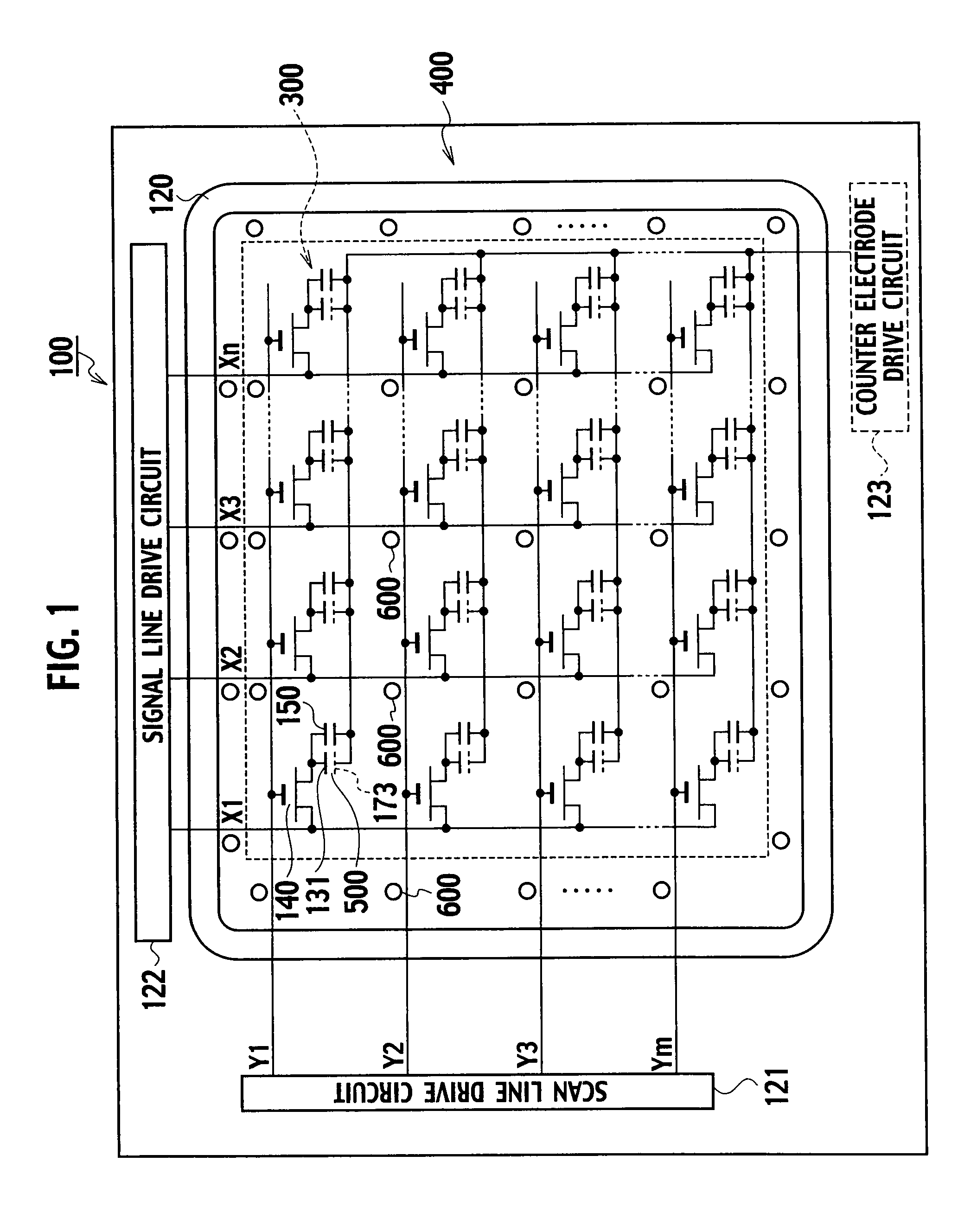
[0022]A plan view in FIG. 1 schematically shows a configuration of an array substrate of a liquid crystal display device according to a first embodiment of the present invention. A display region 300 indicated by a dotted line is provided on an array substrate 100. A peripheral region 400 is provided around the display region 300. In the peripheral region 400, an adhesive 120 is disposed seamlessly so as to surround the display region 300. When injecting liquid crystal, a predetermined amount of the liquid crystal is dropped into the region surrounded by the adhesive 120 in accordance with a one drop fill method. Thereafter, the array substrate 100 and another opposed substrate are assembled together.

[0023]On the array substrate 100, m pieces of scan lines Y1 to Ym (hereinafter collectively referred to as scan lines Y) and n pieces of signal lines X1 to Xn (hereinafter collectively referred to as signal lines X) are arranged orthogonally to one another. A pixel TFT (thin film transi...

second embodiment

[0041]Next, a liquid crystal display device according to a second embodiment of the present invention will be described. Basic configurations of this liquid crystal display device are similar to those explained in the first embodiment. Accordingly, a difference from the first embodiment will be mainly described below.

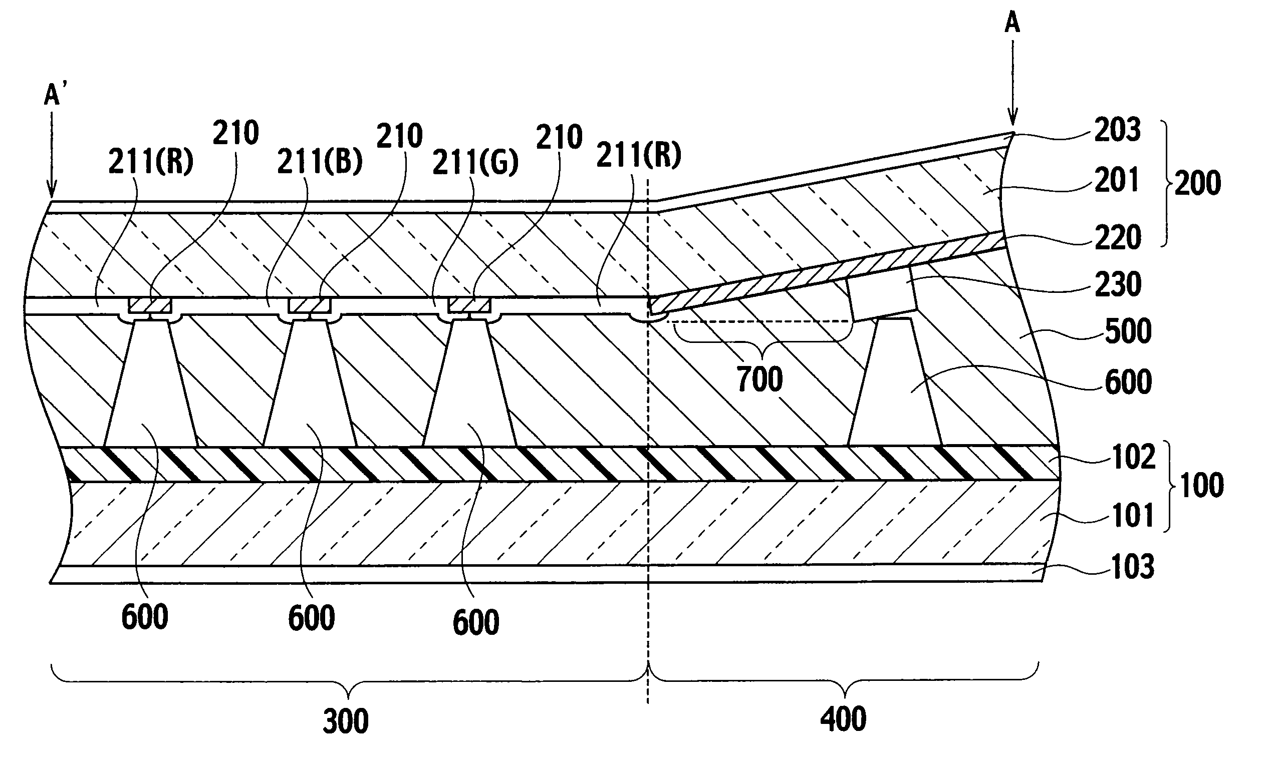
[0042]As shown in FIG. 4, a difference of this embodiment from the first embodiment is in that structural objects 110 which are higher than the spacers 600 are disposed in the peripheral region 400. The structural objects 110 are disposed on the array substrate 100. The structural objects 110 are made of the same material as the material of the spacers. In this configuration, both of the substrates are supported by the spacers 600 in the display region 300, while the substrates are supported by the structural objects 110 in the peripheral region 400. In this way, the substrate surface of the counter substrate 200 in the peripheral region 400 is gently inclined in the di...


PUM

PropertyMeasurementUnit
angleaaaaaaaaaa
heightaaaaaaaaaa
pressureaaaaaaaaaa

Abstract

Structural objects are disposed in a peripheral region in positions opposed to spacers. In this way, a substrate surface of a counter substrate in the peripheral region is gently inclined in a direction away from a liquid crystal layer. In this way, it is possible to prevent unevenness in display attributable to a difference in a cell gap between a display region and the peripheral region.

Description

CROSS REFERENCE TO RELATED APPLICATIONS[0001]This application is based upon and claims the benefit of priority from Japanese Patent Application No. 2007-136812 filed on May 23, 2007; the entire contents of which are incorporated herein by reference.BACKGROUND OF THE INVENTION[0002]1. Field of the Invention[0003]The present invention relates to a liquid crystal display device, and more specifically to a technique suitable for a liquid crystal display device formed by sticking substrates together in accordance with a one drop fill method.[0004]2. Description of the Related Art[0005]A liquid crystal display device has a structure in which liquid crystal is interposed between two glass substrates disposed to face each other and stuck together by using an adhesive. To achieve a uniform cell gap (a thickness of a liquid crystal layer), plastic beads having even grain sizes are dispersed between the substrates. In recent years, there is known a technique to maintain a uniform cell gap by f...

Claims


Application Information

Patent Timeline
Patent Type & Authority Patents(United States)
IPC IPC(8): G02F1/1339
CPCG02F1/13394G02F1/1341G02F2001/133388G02F2001/13396G02F2001/13415G02F1/133388G02F1/13415G02F1/13396G02F1/133G09G3/36
Inventor FUKUOKA, NOBUKOIMAKAWA, MASANORITAKEDA, ARIHIROMORIMOTO, HIROKAZU
Owner JAPAN DISPLAY CENTRAL CO LTD
Why Eureka
Try Eureka