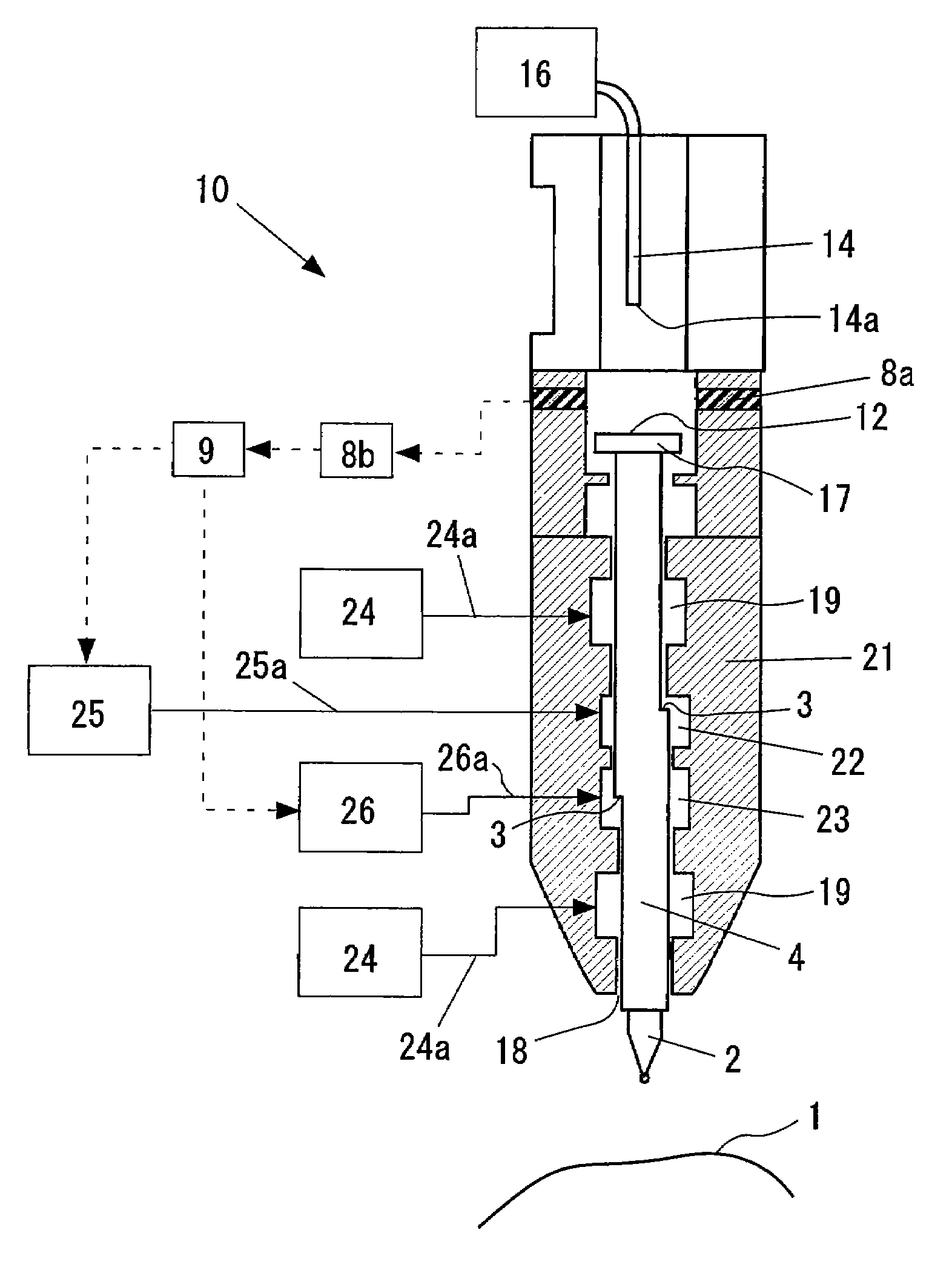
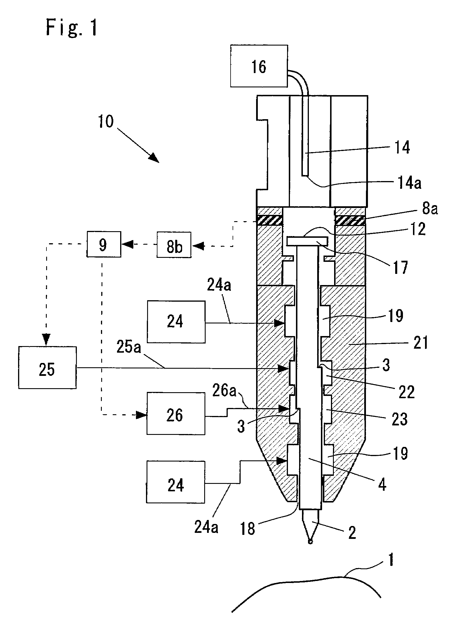
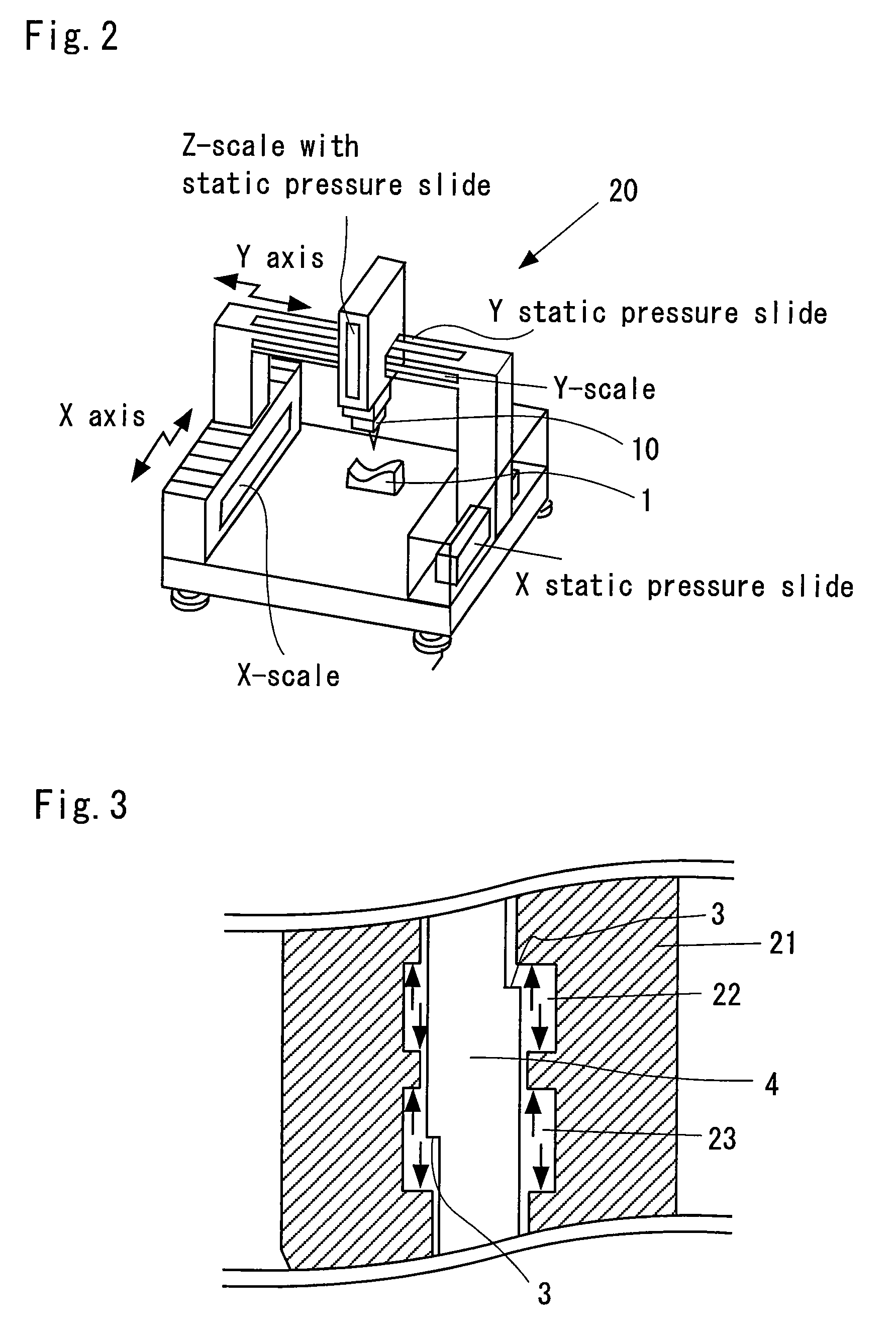
Micro force measurement device, micro force measurement method, and micro surface shape measurement probe
a micro-force measurement and micro-force technology, applied in mechanical measuring arrangements, instruments, manufacturing tools, etc., can solve the problems of reducing the accuracy of the measurement method, and reducing the cost of measurement, so as to prevent the breakage of the probe member
- Summary
- Abstract
- Description
- Claims
- Application Information
AI Technical Summary
Benefits of technology
Problems solved by technology
Method used
Image
Examples
example 1
CONSTITUTION EXAMPLE 1
[0125]To control the contact pressure between the probe member 2 and the object 1 to be measured with a higher precision, the probe member 2 is elastically displaced by the contact pressure, the contact pressure is calculated from this elastic displacement and a spring constant of the probe member 2, and the control device 9 can control the pressing device based on this calculated contact pressure to adjust the pressing force. In consequence, the contact pressure can further minutely be adjusted as compared with a conventional example.
[0126]This constitution example is shown in FIG. 10. As shown in FIG. 10, an elastic article 2c made of a rubber or a (hollow) elastic resin is sandwiched between the probe member 2 and the probe shaft 4 to connect the contact to the shaft. Furthermore, a reflective surface 2d of the probe shaft 4 directed rearwards in the axial direction is formed on the back surface of the probe member 2.
[0127]With the probe member 2 constituted...
example 2
CONSTITUTION EXAMPLE 2
[0133]Moreover, in a case where the surface of the object 1 to be measured is inclined with respect to the probe member 2 when the probe member 2 comes into contact with the object 1 to be measured, there is a problem that the lateral displacement occurs, as mentioned above. To solve this problem, according to the embodiment of the present invention, as shown in FIGS. 13A and 13B, the probe member 2 has a constitution in which the probe member 2 is elastically deformed s so as to prevent the lateral displacement. FIG. 13A is a side view of the probe member 2 for preventing the lateral displacement, and FIG. 13B is a cross sectional view, taken along the A-A arrow line of FIG. 13A. In the example of FIGS. 13A and 13B, the probe member 2 is constituted of four elastically deformable cantilevers which are arranged symmetrically with respect to the center of the probe member 2 and which come into contact with the object 1 to be measured in substantially the same po...
PUM
| Property | Measurement | Unit |
|---|---|---|
| frequency | aaaaa | aaaaa |
| antiresonant frequency | aaaaa | aaaaa |
| antiresonant frequency | aaaaa | aaaaa |
Abstract
Description
Claims
Application Information
 - R&D
- Intellectual Property
- Life Sciences
- Materials
- Tech Scout
- Unparalleled Data Quality
- Higher Quality Content
- 60% Fewer Hallucinations
Browse by: Latest US Patents, China's latest patents, Technical Efficacy Thesaurus, Application Domain, Technology Topic, Popular Technical Reports.
© 2025 PatSnap. All rights reserved.Legal|Privacy policy|Modern Slavery Act Transparency Statement|Sitemap|About US| Contact US: help@patsnap.com


