
Integrated electronic circuitry comprising tunable resonator

a technology of integrated electronic circuitry and resonators, which is applied in the direction of impedence networks, single resonant circuits with varying inductance/capacitance only, continuous tuning, etc., can solve the problem of difficult integration with other electronics circuitry in the same, the filter tuning based on such resonators is difficult to achieve, and it becomes necessary to allocate an expensive surface of silicium

Active Publication Date: 2010-03-23
STMICROELECTRONICS SRL
View PDF17 Cites 4 Cited by
  • Summary
  • Abstract
  • Description
  • Claims
  • Application Information

AI Technical Summary

Benefits of technology

[0017]An embodiment provides a circuit comprising a tunable integrated resonator, of the SAW or BAW type, which is easy to integrate in a semiconductor substrate and which provides a wide number of functions and possibilities.
[0018]Another embodiment provides a tunable resonator circuit, based on a BAW or a SAW type resonator, which does not require any tuning inductor and does not jeopardize the quality factor of the resonator and which further does not generate any parasitic anti-resonant frequency.

Problems solved by technology

They are however likely to serve in many other applications but the clear obstacle to their general use reside in the difficulty to be integrated with other electronics circuitry in a same semiconductor product.
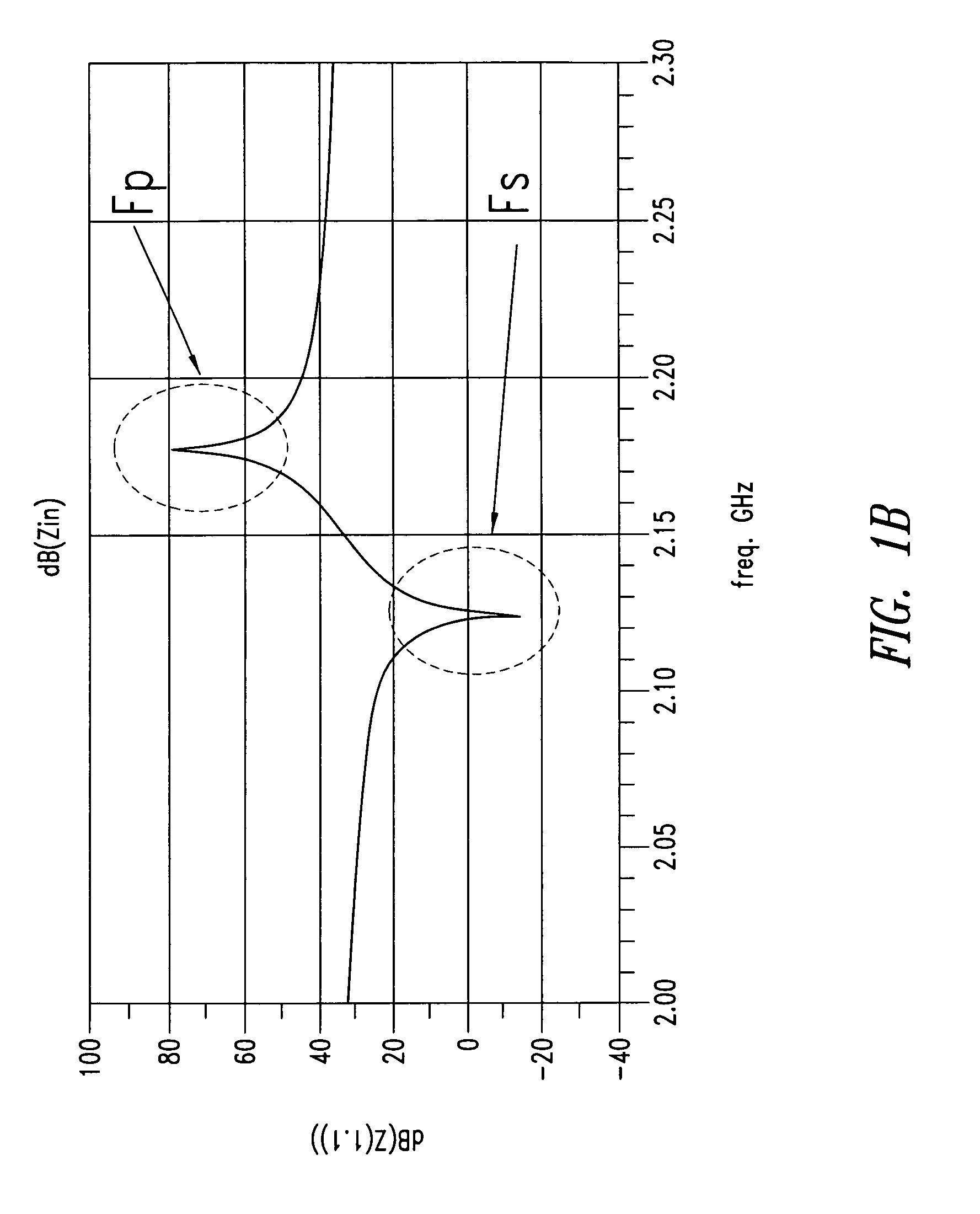
Generally speaking, the difference between the anti-resonance frequency and the resonance frequency in a filtering circuit defines the pass band of that circuit and the tuning of the filter based on such resonators shows to be difficult to achieve.
Firstly, that circuit requires, for every BAW resonator, one inductor—e.g., an integrated spiral inductor - which is known to occupy a non negligible surface on the semi-conductor substrate. When a complex band pass filter has to be carried out, based on a set of components illustrated in FIG. 2A, it becomes necessary to allocate an expensive surface of silicium.
Secondly, integrated inductors on silicium substrate have a low quality factor resulting in additional losses and jeopardizing the performance of the BAW resonators. Inductors with higher quality factors do exists but they required a different substrate, such as a glass substrate, and this is a clear obstacle for the purpose of achieving a low costs manufacturing process.

Method used


Image

  • Integrated electronic circuitry comprising tunable resonator
  • Integrated electronic circuitry comprising tunable resonator
  • Integrated electronic circuitry comprising tunable resonator

Examples


first embodiment

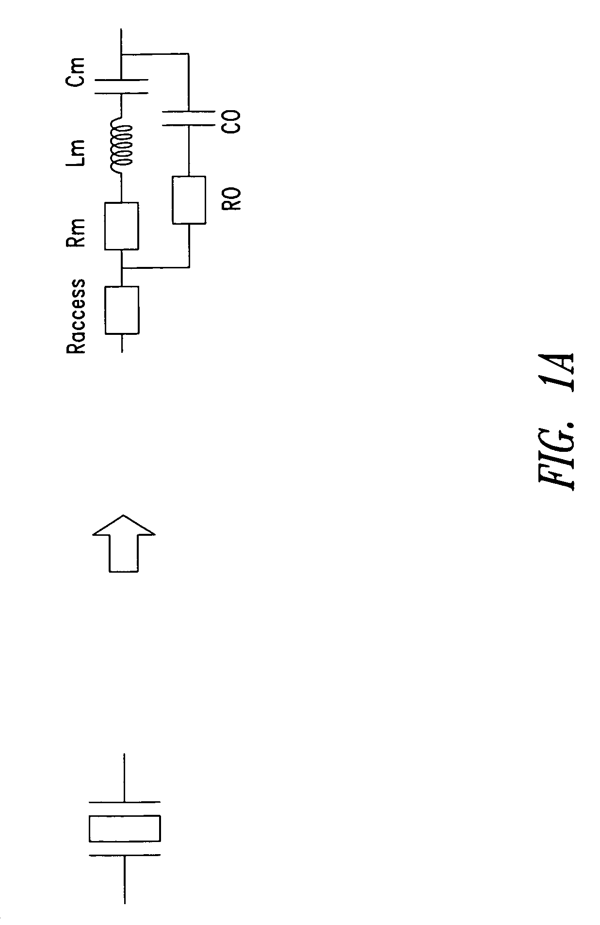
[0056]FIG. 3A illustrates a first embodiment showing a simplified resonance circuit which comprises, in parallel with a resonator BAW 31, a negative capacity Cneg 32.

[0057]Surprisingly, it has been noticed that one may obtain the same result than the one obtained with one inductor in the known circuit simply by using an active circuit which has the behavior of a negative capacity Cneg.

[0058]Simulations have shown indeed that, as a function of the absolute value of this negative capacity, one may cause the shifting, either to the right or to the left, of the anti-resonance frequency Fp while maintaining unchanged the series resonance frequency, as this is illustrated in FIGS. 3B and 3C.

[0059]More particularly, FIG. 3B shows that when the absolute value of Cneg is lower than the internal parameters C0+Cm of the BAW resonator, then the anti-resonance frequency is shifted to the right.

[0060]Conversely, when the absolute value of Cneg is higher than C0+Cm, the anti-resonance frequency is...

second embodiment

[0062]FIG. 4A illustrates a tunable resonator circuit which comprises, in series with the circuit of FIG. 3A, a tunable capacity component, such as a varactor for instance having a variable capacity Cv.

[0063]One thus obtains a circuit which provides numerous possibilities of tunings in accordance to the value of Cneg.

[0064]FIGS. 4B to 4D respectively illustrate the characteristics curves of the second embodiment in accordance with the negative capacity Cneg with respect to the values C0+Cm and C0+Cm+Cv.

[0065]When the absolute value of Cneg is lower than C0+Cm, then one notices the shifting to the right of the two series and parallel resonance frequencies, as this is illustrated in FIG. 4B.

[0066]When the absolute value of Cneg is higher than C0+Cm+Cv, the series resonance frequency Fs and the parallel resonance frequency Fp are both shifted to the left, as illustrated in FIG. 4C.

[0067]At last, when the absolute value of Cneg is comprised within C0+Cm and C0+CM+Cv, one notice that the...

third embodiment

[0069]FIG. 5A illustrates a third embodiment which comprises a negative capacity Cv coupled in series with the BAW resonator. As this is seen in FIGS. 5B and 5C, one can shift, respectively to the rights or to the left, the series resonance frequency. Thus, when the absolute value of Cneg is lower than C0+Cm, the negative capacity causes the shifting to the right of the series resonance frequency, as this is illustrated in FIG. 5B. Conversely, when the absolute value of Cneg is higher than C0+Cm, one observes the shifting to the left of the series resonance frequency, as this is shown in FIG. 5C.


PUM


Abstract

An electronic circuit includes: an acoustic resonator of BAW or SAW type, said resonator having a series resonance frequency and a parallel resonance frequency; an active circuit which is coupled in parallel to said acoustic resonator, said active circuit having a negative capacity acting on the parallel resonance frequency of said resonator.

Description

TECHNICAL FIELD[0001]The present disclosure generally relates to microelectronic circuits and more particularly but not exclusively to an integrated electronic circuitry comprising a tunable resonator.BACKGROUND INFORMATION[0002]Acoustic resonators are components which were subject of numerous technical studies. Conventionally, one distinguishes between Surface Acoustic Resonator (SAW) and Bulk Acoustic Resonator (BAW). In SAWs, the acoustic resonator is located on the surface of a semiconductor product while, in BAWs, it lays inside a volume delimited between a lower electrode and a higher electrode so that the acoustic wave develops in this volume.[0003]Because of their efficiency, acoustic resonators are frequently used in radio frequency (RF) filtering and in particular in mobile telephony. They are however likely to serve in many other applications but the clear obstacle to their general use reside in the difficulty to be integrated with other electronics circuitry in a same se...

Claims


Application Information

Patent Timeline
Patent Type & Authority Patents(United States)
IPC IPC(8): H03H9/02H03H11/00H03B5/36
CPCH03H9/17H03H9/25H03J3/20
Inventor CATHELIN, ANDREIARAZAFIMANDIMBY, STEPHANETILHAC, CYRILLE
Owner STMICROELECTRONICS SRL
Learn More