
Side airbag connector assembly

a connector and airbag technology, applied in the field of side airbags, can solve the problems of increasing the amount of time required achieve the effects of less time for the airbag to exit the seat, less time for the airbag to be deployed, and more control of the deployment process

Active Publication Date: 2010-03-23
PISTON INTERIORS LLC
View PDF41 Cites 13 Cited by
  • Summary
  • Abstract
  • Description
  • Claims
  • Application Information

AI Technical Summary

Benefits of technology

[0014]One advantage of the present invention may be that it provides a novel and improved connector assembly for use in a seat of a vehicle having a side airbag.
[0015]Still a further advantage of the present invention may be that it allows for a quicker and easier deployment of an airbag from the vehicle seat.
[0016]Still another advantage of the present invention may be that it provides for a clip member and rod to be used in connecting an airbag chute around a seat frame and airbag module.
[0017]Still yet another advantage of the present invention may be that the connector assembly has a clip member and rod that may provide a visual and / or audible confirmation of a positive lock therebetween.
[0018]Still another advantage of the present invention is that it may provide for a tear along a seam to occur more quickly and completely thus allowing for more control of the deployment process of the airbag from the seat.
[0019]Still another advantage of the present invention may be that the connector assembly may reduce the complexity of manufacturing and installing a side airbag module within a vehicle seat.

Problems solved by technology

Many of these prior art seat side airbags penetrate the seat cover by tearing open the sewn seam in the seat cover.
However, there have been problems in the prior art with such systems such as but not limited to ballooning of the seat cover occurring prior to failure of the seam, an increased amount of time required for the airbag to exit the seat, and the airbag deploying in a position that does not properly place the airbag between the individual and the interior surfaces of the vehicle.
Furthermore, there also have been problems with prior art seat side airbag assemblies in verifying that the seat side airbag assembly is properly arranged within the seat.

Method used


Image

  • Side airbag connector assembly
  • Side airbag connector assembly
  • Side airbag connector assembly

Examples


Embodiment Construction

)

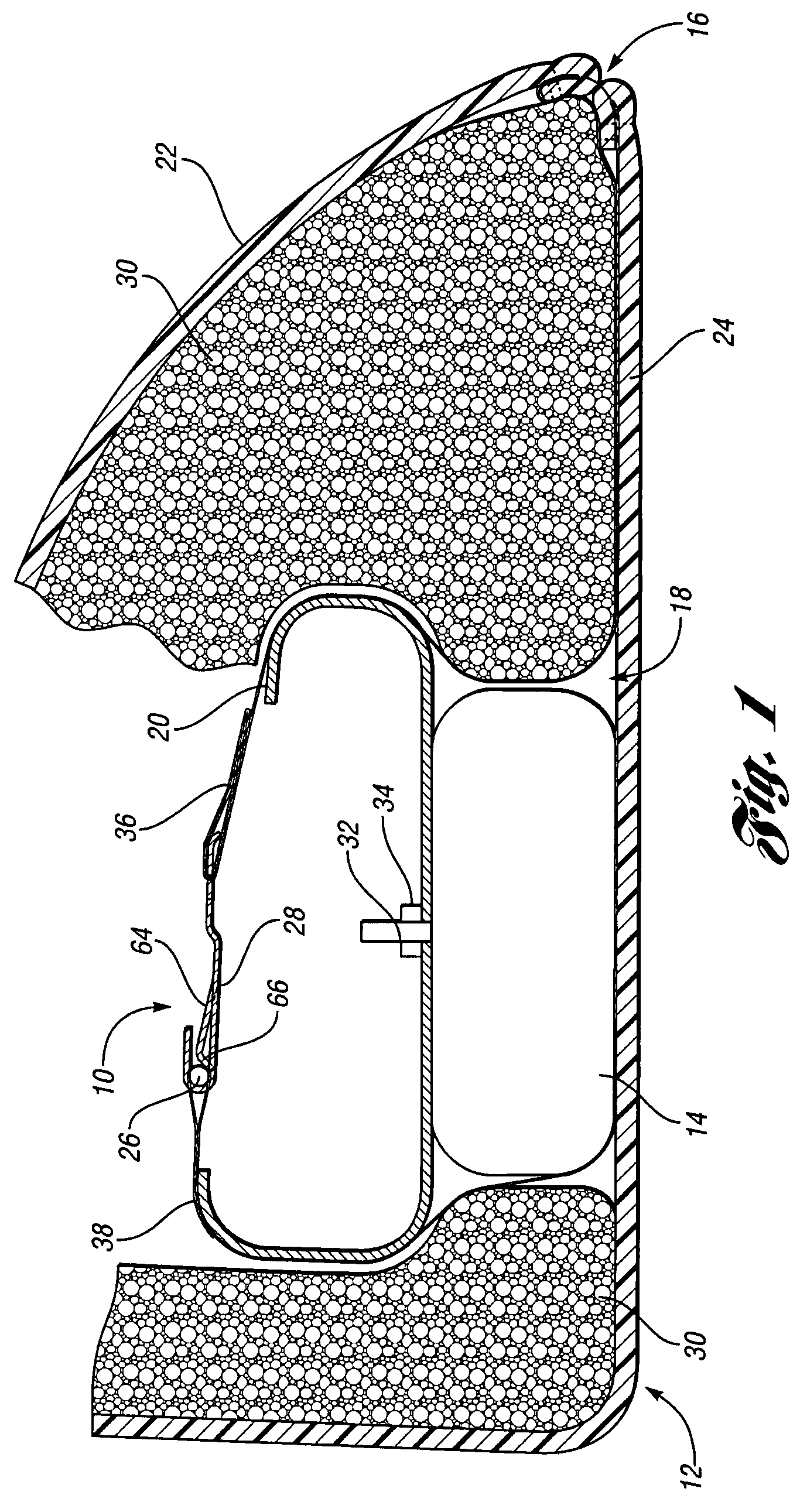
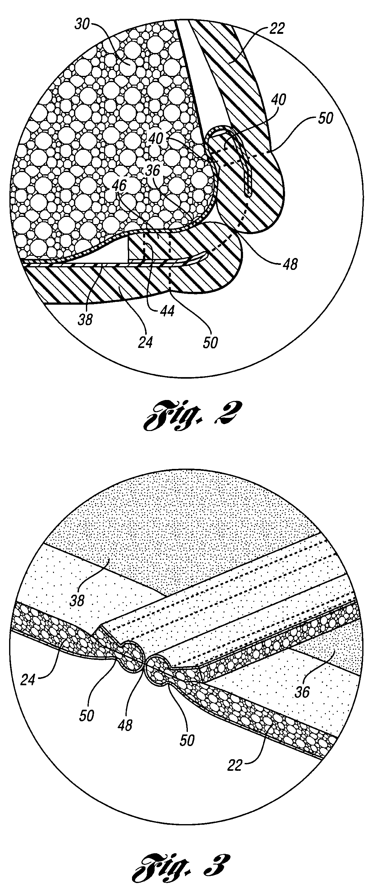
[0027]Referring to the drawings, a connector assembly 10 for use in a seat 12 of a vehicle having a side airbag module 14 arranged therein is disclosed. It should be noted that the upholstery seam 16 shown in the drawings is for use on a seat 12 having a side airbag 14 deployed therefrom. It should further be noted that any other type of seam 16 apart from that shown in the drawings may also be used in connection with a connector assembly 10 and airbag chute 18 according to the present invention. In one contemplated embodiment, a continuous side airbag seam 16 as described and disclosed in a patent application filed by the present Applicant may also be used. That application having provisional patent application No. 60 / 931,964 is hereby incorporated by reference. The present invention may be used on any type of seat and with any type of seam and it may be used with any type of material, such as laminate backed material, non-laminate backed material, or any other known covering mate...


PUM


Abstract

A connector assembly for use with a side airbag having a tearable seam in a vehicle seat is disclosed. The connector assembly includes a clip member having a slot near one end thereof and an inner chute connected to the clip member via the slot. The connector assembly also includes a rod releaseably secured to the clip member. An outer chute is connected to the rod and the seam on the opposite end thereof. The chute will allow for proper guidance of the airbag during deployment from the seat in a crash situation.

Description

BACKGROUND OF THE INVENTION[0001]1. Field of the Invention[0002]The subject invention generally relates to side airbags, and more particularly relates to a side airbag connector assembly for use in an automotive seat using a chute to direct the airbag during deployment thereof.[0003]2. Description of Related Art[0004]It is well known in the prior art of automotive vehicles to provide an airbag assembly for protection of a vehicle occupant. These prior art airbag assemblies typically are deployed from in front of a person or from a seat or roof line of an automotive vehicle. The airbag generally includes an inflatable cushion structure in communication with a gas emitting inflator. When predetermined vehicle conditions occur, an airbag cushion is deployed outwardly from its stored position in a dashboard, roof, or seat into a position between the occupant and the interior portions of a vehicle against which the occupant might otherwise come in contact with. The use of the airbag cush...

Claims


Application Information

Patent Timeline
Patent Type & Authority Patents(United States)
IPC IPC(8): B60R21/20
CPCB60R21/207B60R21/217B60R2021/161B60R2021/23146
Inventor WIECZOREK, JOSEPH P.HAMLIN, TIMOTHY O.BUSHA, BRYAN
Owner PISTON INTERIORS LLC
Learn More