
Overhead-supported net system

a net system and support technology, applied in the field of net systems, can solve the problems of time-consuming installation, complicated installation and disassembly of the game net support, and more than two people's safety

Active Publication Date: 2007-08-16
GARED HLDG
View PDF16 Cites 9 Cited by
  • Summary
  • Abstract
  • Description
  • Claims
  • Application Information

AI Technical Summary

Benefits of technology

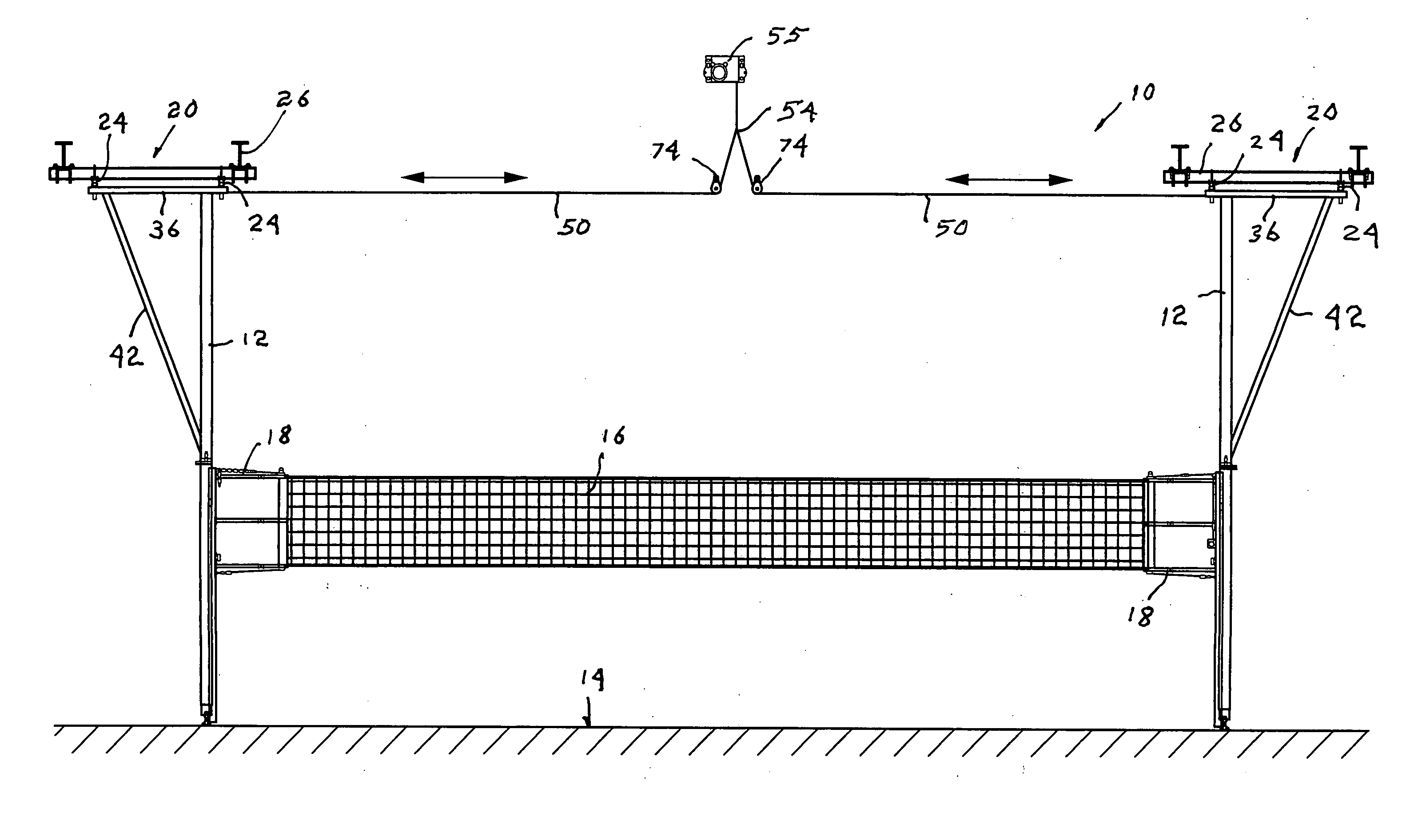
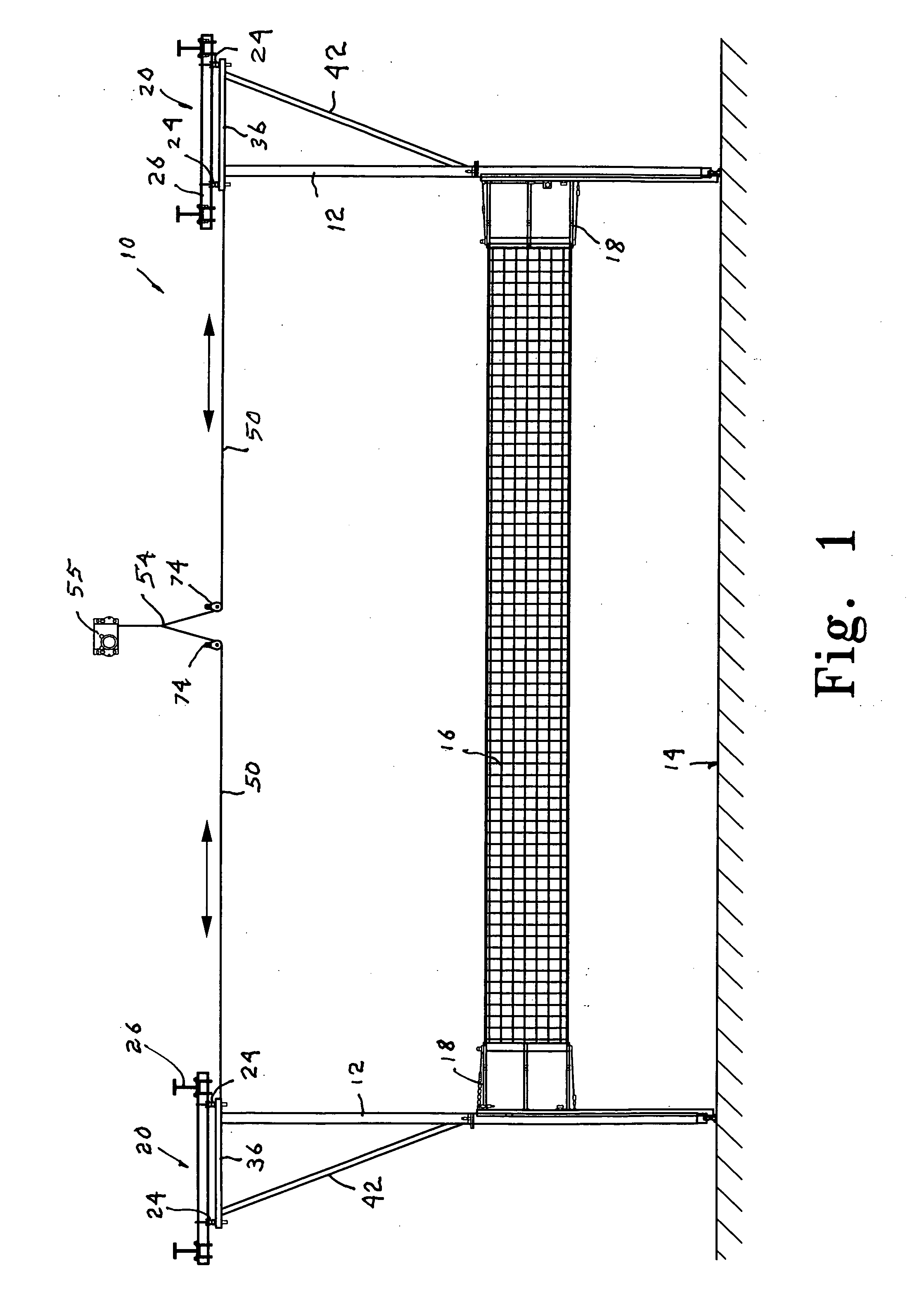
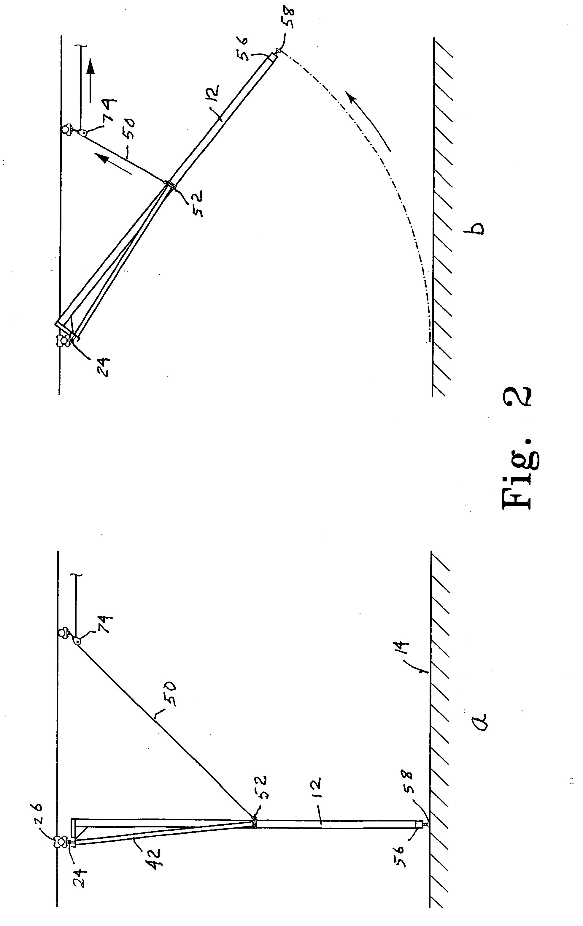
[0008] These several needs are satisfied by a net system having a pair of parallel poles vertically positionable on opposite sides of a playing area with a net coupled to the pair of poles to lie in a plane including the pair of poles. Supports are fixed to an upper end of each of the pair of poles including pivot members positioned to one side of the plane containing the net and pair of poles. Coupling members couple the pivot members to the ceiling structure covering the playing area. The pivot members allow the poles and net to be pivotally displaced from a nearly horizontal non-playing storage position above a playing surface on one side of the playing area to a vertical playing position in a vertical plane bifurcating the playing area. The position of the pivot members to one side of the plane containing the net and poles ensures a downward force on the playing surface by lower ends of the poles when the poles are in the vertical playing position.
[0010] Net support members can be coupled to each of the poles and to the net, with the net support members being movable with respect to the poles so that the net can be situated at any selected position between a tennis position with the lower margin of the net adjacent to the playing surface upward to a men's volleyball position. This vertical movability of the net with respect to the poles allows the same facility to be used for a wide variety of sports requiring a net bifurcating a playing area. The pivotal arrangement of the net and poles allow the playing area to be used for even other activities that do not require the presence of a net bifurcating the playing area.
[0011] Deployment of the net system can be accomplished by providing a pair of parallel poles vertically positionable on opposite sides of a playing area having a net coupled to the pair of poles to lie in a plane including the pair of poles with supports fixed to an upper end of each of the pair of poles including pivot members positioned on one side of the plane; coupling the pivot members at selected points of a ceiling structure covering the playing area to allow the poles and net to be pivotally displaced from a storage position above the playing surface on one side of the playing area to a vertical playing position in a vertical plane bifurcating the playing area; and adjusting the position of members on the lower end of each of the pair of poles to ensuring a downward force on the playing surface by the lower ends of the poles when the poles are in the vertical playing position. A further vertical adjustment of the net relative to the pair of poles can accommodate the particular standards of a selected sport to be played with the net at a playing position in a vertical plane bifurcating a playing area.
[0012] One feature of the present invention is the defined floor positioning for the poles supporting the net without any sockets or clips in the floor. This feature has the advantage of allowing full use of the playing area when the net and poles are moved to the storage position, which is something not permitted if sockets or clips are required to be installed in the floor. Another feature is the ease with which the system is deployed from the storage position to the playing position, so that a single person can easily and quickly deploy the net support system in position ready for play.

Problems solved by technology

However, the structural details of the system are such that the erection and disassembly of the game net support is rather complicated and may require more than two people to safely accomplish.
But each mounting post must be separately handled, so although installation by a single person is possible, the installation is time consuming.

Method used


Image

  • Overhead-supported net system
  • Overhead-supported net system
  • Overhead-supported net system

Examples


Embodiment Construction

[0024] A net system 10 of the present invention is shown in FIG. 1 to have a pair of parallel poles 12 that are vertically positionable on opposite sides of a playing area 14 with a net 16 coupled to the pair of poles 12. The net 16 can be connected to the poles 12 with tension members 18 that can be adjusted to achieve the desired amount of tension in the net 16. Details of a preferred connection between the poles 12 and the net 16 are discussed below in connection with FIGS. 6 and 9.

[0025] Supports 20 are fixed to an upper end 22 of each of the pair of poles 12. The supports 20 include pivot members 24. Coupling members 26 couple the pivot members 24 to the ceiling structure covering the playing area 14. The supports 20 are shown in FIGS. 3-5 to include a first support member 28 having a first end 30 fixed to the upper end 22 of the pole 12. The first support member 28 extends away from the plane defined by the net 16 and the poles 12 to a second end 32. A flange 34 can be provid...


PUM


Abstract

A net system pivotally displacing a net between a playing position in a vertical plane bifurcating a playing area and a nearly horizontal elevated storage position freeing the playing area for other uses. Parallel poles are located on opposite sides of the playing area with a net coupled to the pair of poles to lie in a plane including the pair of poles. Coupling members couple pivot members to ceiling structure over the playing area. Supports have proximal ends fixed to an upper end of each of the pair of poles and a distal end extending on a common side of the plane defined by the net and poles. The distal end of the supports are coupled to the pivot members to allow the poles and net to be pivoted about an axis lying parallel to but outside the plane defined by the net and poles, the position of the pivot members ensuring a downward force on the playing surface by lower ends of the poles when the poles are in the vertical playing position.

Description

BACKGROUND OF THE INVENTION [0001] The present invention relates to net systems, consisting generally of a net suspended between a spaced pair of poles and supports for the poles. The present invention relates particularly to such a net system that is supported from a ceiling or roof structure and can be moved between a vertical playing position within a playing area and an elevated storage position that frees the playing area for other uses. [0002] The net system of the present invention can be used in connection with the sports of volleyball, tennis and badminton, as well as other sports played with a vertical net bifurcating the playing area, which can be within a gymnasium or other sports facility. Often the sports facility is a multi-use facility in which other sports can be played that do not require such a vertical net bifurcating the playing area. It is therefore desirable that the net be easily and quickly located at a desired playing position within the facility, and just ...

Claims


Application Information

Patent Timeline
IPC IPC(8): A63C19/06A63B61/02A63B61/00
CPCA63B61/003A63B61/02A63B2243/0095A63B2243/0083A63B2210/56A63B2102/02
Inventor CONNERLEY, JAMES J.SNOW, ANDREW T.
Owner GARED HLDG
Learn More