
Interpolation and decimation using newton polyphase filters

a polyphase filter and interpolation technology, applied in the field of digital signal processing, can solve the problems of degrading the stop-band attenuation of the filter, high filter side, etc., and achieve the effect of reducing computational complexity, further simplifying the filter structure, and reducing the associated computational complexity

Active Publication Date: 2010-03-16
STMICROELECTRONICS LTD
View PDF14 Cites 2 Cited by
  • Summary
  • Abstract
  • Description
  • Claims
  • Application Information

AI Technical Summary

Benefits of technology

The present invention provides improved polyphase filter configurations and methods for designing such filters. The invention addresses the trade-off between filter performance and the number of filter coefficients and required quantization. The disclosed methods and devices offer a better complexity / performance trade-off than currently-available filters. The invention also simplifies the design process and reduces the computational complexity required for the filter. The invention provides filters with high stop-band attenuation and a simplified design process. The invention also provides a simplified design for a multistage interpolation filter. Overall, the invention provides filters with improved performance and reduced complexity.

Problems solved by technology

Failure to allocate a sufficient number of bits to represent the coefficients typically results in high filter side-lobes, which degrade the filter stop-band attenuation.

Method used


Image

  • Interpolation and decimation using newton polyphase filters
  • Interpolation and decimation using newton polyphase filters
  • Interpolation and decimation using newton polyphase filters

Examples


Embodiment Construction

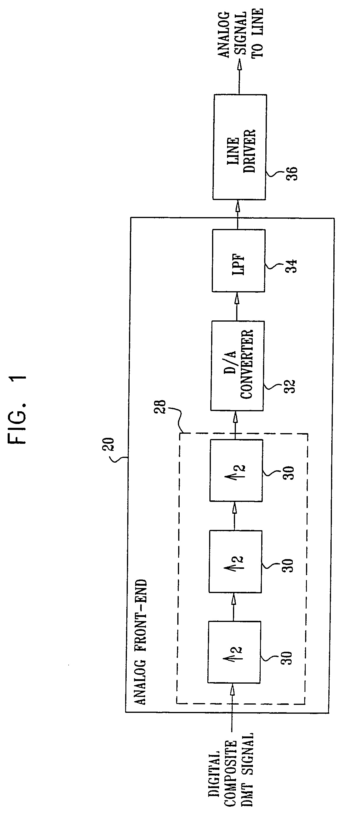
[0067]FIG. 1 is a block diagram that schematically illustrates parts of an ADSL transmitter, in accordance with an embodiment of the present invention. In this embodiment, polyphase interpolation filters are used for multiplying the sampling rate of a digital Discrete Multi-Tone (DMT) signal that comprises multiple modulated tones, according to the ADSL specification. (Additional details regarding the different DSL standards can be found at www.dslforum.org.)

[0068]The ADSL transmitter shown in FIG. 1 comprises an analog front-end (AFE) 20 that receives a digital composite DMT signal and converts it to an analog signal suitable for transmission over a telephone line. The AFE is typically implemented in a mixed-signal Application-Specific Integrated Circuit (ASIC). The AFE comprises a multistage interpolation filter 28 comprising three interpolation filters 30. The interpolation filters are implemented using methods described herein. Multistage interpolation filters are further explai...


PUM


Abstract

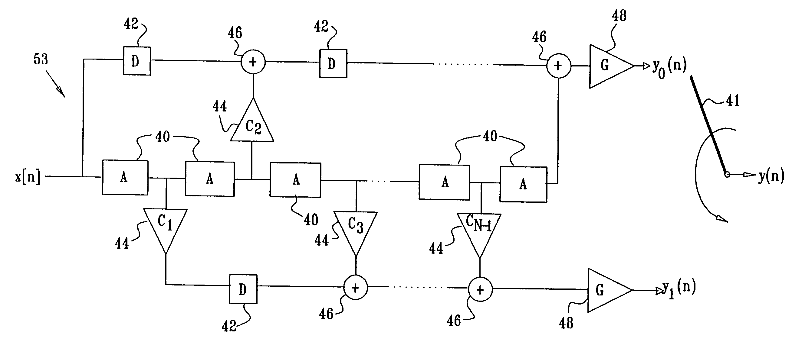
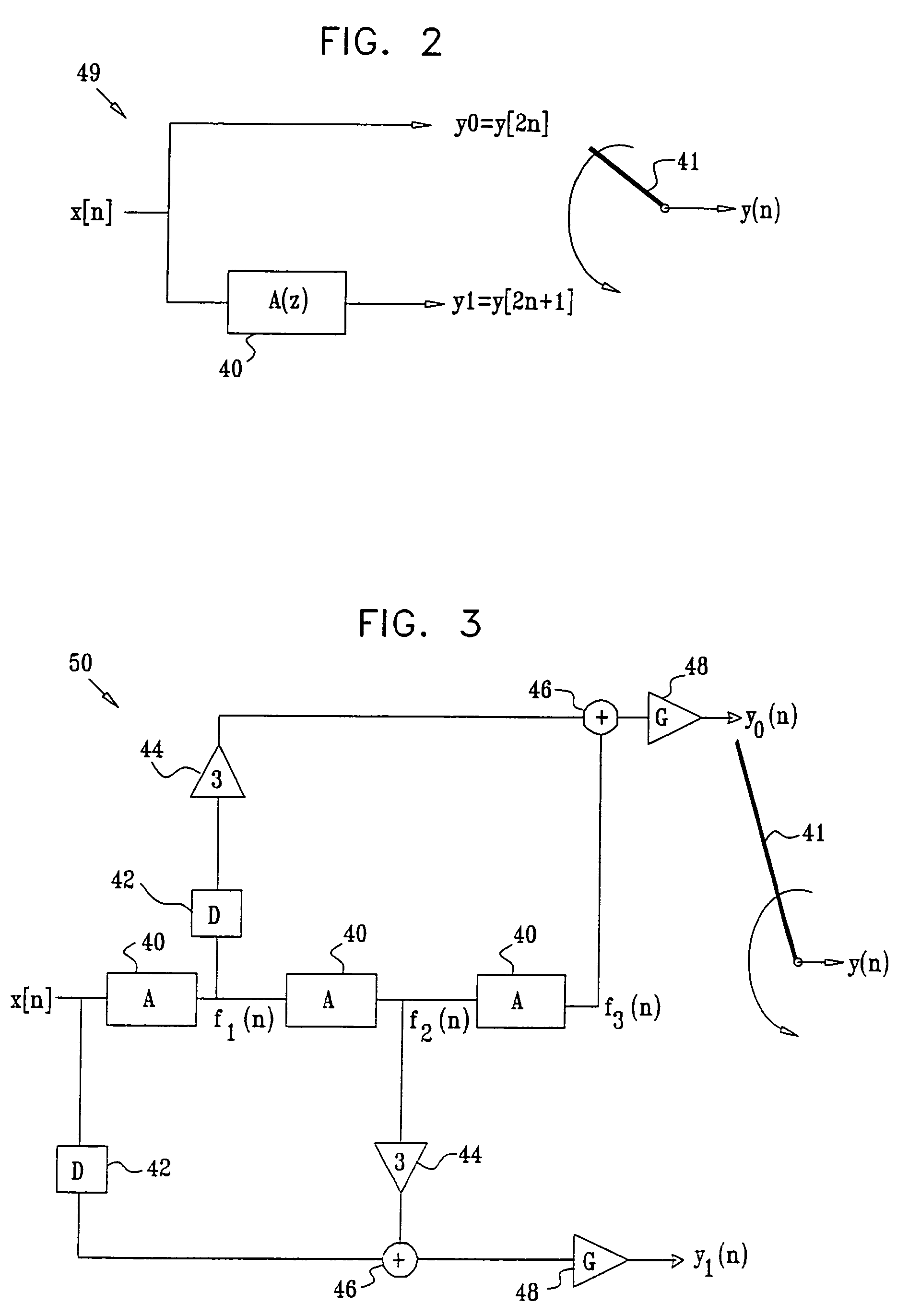
An interpolation filter for interpolating a digital signal includes a cascade of template filters, each having an identical template transfer function A(z), which is arranged to receive and filter an input sequence representing the digital signal sampled at an input sampling rate. Ancillary circuitry is coupled to the cascade so as to produce first and second phase outputs. A multiplexer is arranged to multiplex the phase outputs in order to generate an output sequence having an output sampling rate equal to twice the input sampling rate.

Description

FIELD OF THE INVENTION[0001]The present invention relates generally to digital signal processing, and particularly to methods and devices for digital interpolation and decimation.BACKGROUND OF THE INVENTION[0002]In many signal processing applications it is required to modify the sampling rate of a digitally-represented signal. Sampling rate conversion commonly involves the use of interpolation or decimation filters. An interpolation filter accepts a sequence of input samples having an input sampling rate and produces a sequence of output samples having a higher output sampling rate. The ratio between the output and input sampling rates is referred to as the interpolation factor. Similarly, a decimation filter accepts an input sequence and produces an output sequence having a lower output sampling rate. The ratio between the input and output sampling rates is referred to as the decimation factor.[0003]Interpolation and decimation filters are described in a variety of publications, su...

Claims


Application Information

Patent Timeline
Patent Type & Authority Patents(United States)
IPC IPC(8): G06F17/17
CPCH03H17/0275H03H17/0657H03H17/0664
Inventor CHISKIS, ALEXANDER
Owner STMICROELECTRONICS LTD
Learn More