Image processing apparatus, image reading apparatus and image recording apparatus
a technology of image processing and reading apparatus, which is applied in the direction of electrical devices, instruments, computing, etc., can solve the problems of poor determination accuracy, high manufacturing cost of image processing apparatus, and complicated comparison circuit in image processing apparatus, and achieve the effect of accurately detecting a plurality of detection patterns
- Summary
- Abstract
- Description
- Claims
- Application Information
AI Technical Summary
Benefits of technology
Problems solved by technology
Method used
Image

Examples
embodiment 1
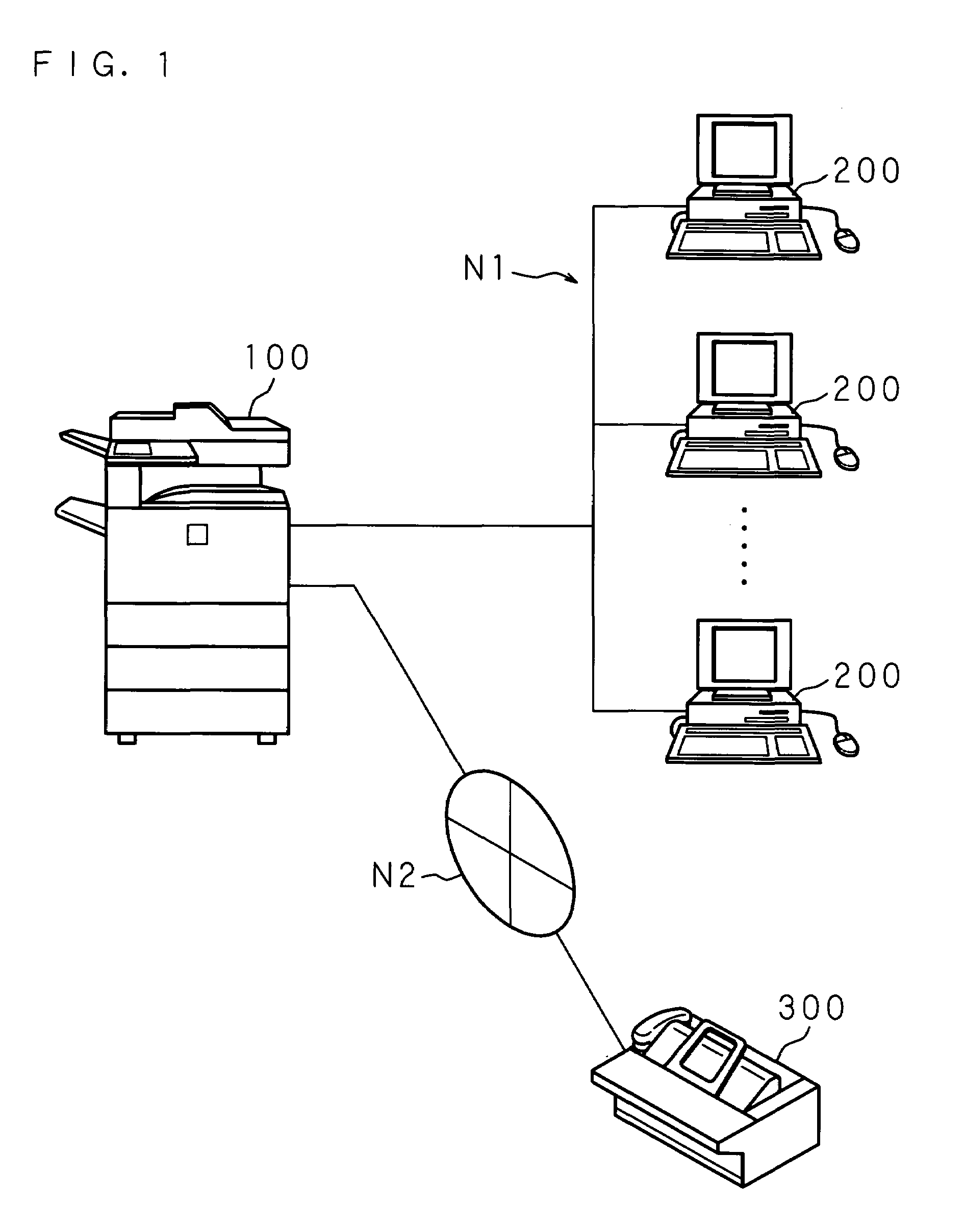
[0053]FIG. 1 is a schematic view showing the structure of an image recording system of the present invention including a digital multi-function machine of this embodiment. In FIG. 1, 100 represents a digital multi-function machine of this embodiment to which information processors 200, 200, . . . , 200 such as a personal computer and a work station, are connected through a communication network N1, and an external facsimile machine 300 is connected through a facsimile communication network N2.
[0054]A driver program (printer driver) for using the digital multi-function machine 100 through the communication network N1 is preinstalled in the information processor 200 so that an output process is executed by generating print data and transmitting the generated print data by the printer driver to the digital multi-function machine 100. When the digital multi-function machine 100 receives the print data transmitted from the information processor 200, it generates image data for output acc...
embodiment 2
[0094]In Embodiment 1, after making a determination based on the first criterion, the second criterion is called, if necessary, and a determination is made based on the second criterion. However, it may be possible to call both the first criterion and the second criterion in advance.
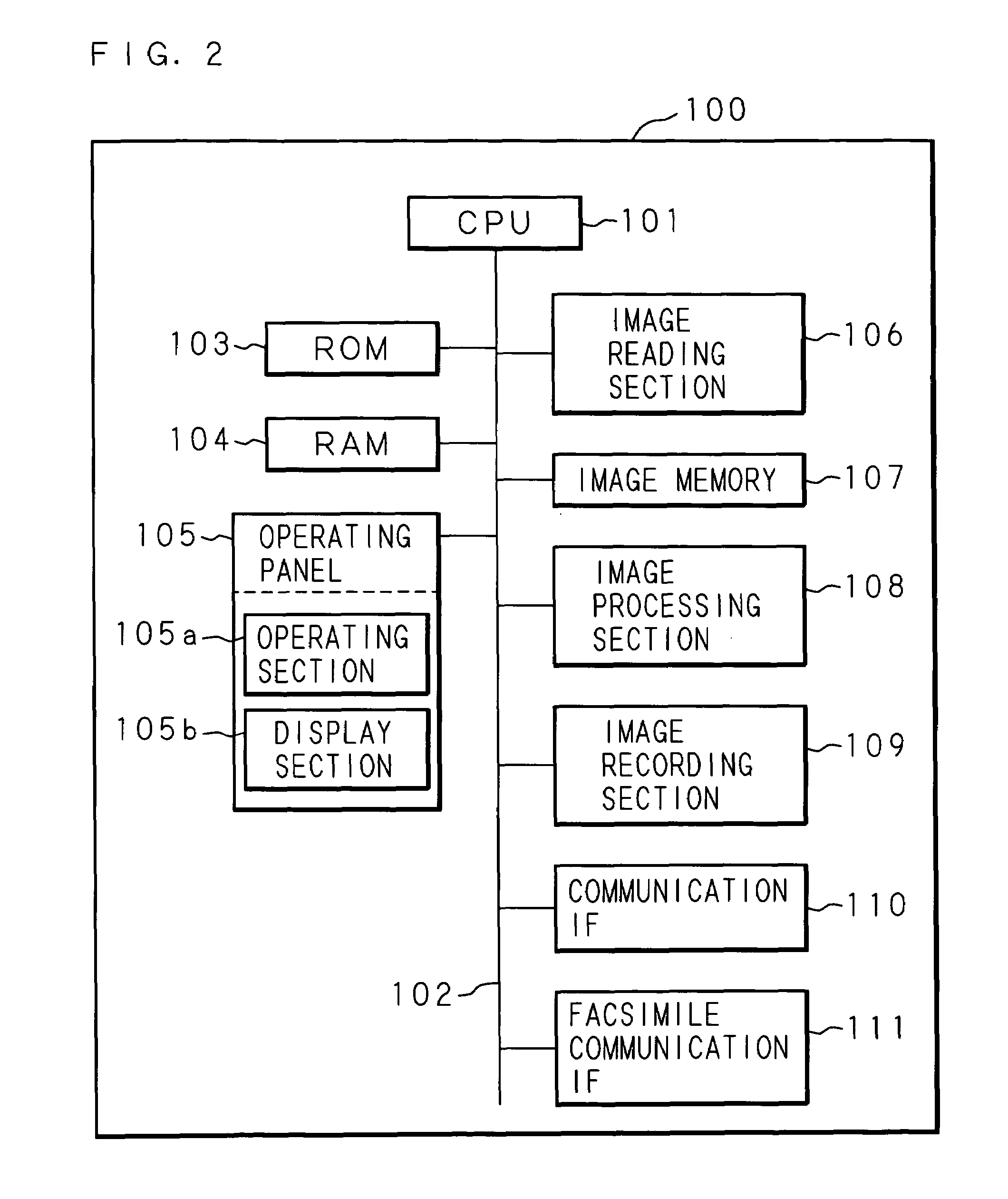
[0095]FIG. 12 is a flowchart for explaining the processing steps for copying a document. First, the CPU 101 of the digital multi-function machine 100 monitors information inputted through the operating section 105a of the operating panel 105 and determines whether or not there is an instruction to start reading a document (step S31). When a determination is made that there is not an instruction to start reading (S13: NO), the CPU 101 waits until an instruction to start reading is given.
[0096]When a determination is made that an instruction to start reading a document is given (S31: YES), the CPU 101 controls the image reading section 106 to execute the document reading process (step S32), binarizes the r...
embodiment 3
[0102]In the above-described embodiment, although the first criterion and second criterion are both stored in the memory in the image processing section 108, it may be possible to store only one criterion (for example, the first criterion) in the memory in the image processing section 108, and calculate the other criterion (for example, the second criterion) by arithmetic processing performed by the CPU 101.
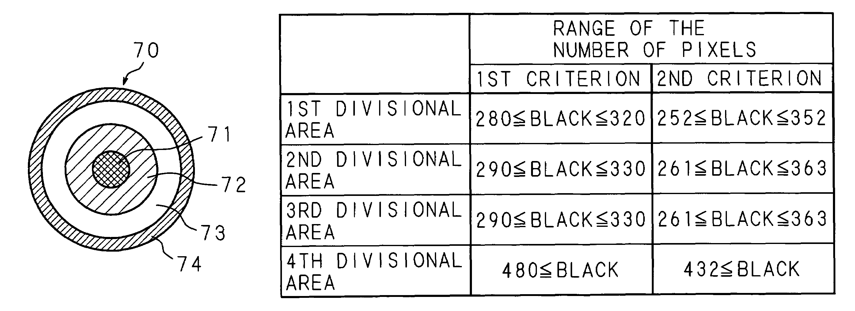
[0103]FIG. 13 is a conceptual view showing a table specifying the divisional areas and the range of the number of pixels. In the example shown in FIG. 13, the range of the number of pixels based on the nth criterion (n=1, 2, 3 . . . ) is arithmetically described. However, in actual practice, only the range of the number of pixels according to the first criterion may be stored, and the second criterion and the following criteria may be obtained by arithmetic processing of the CPU 101 when it is necessary to update the criterion. In other words, when updating the criterion, an oper...
PUM
 Abstract
Description
Claims
Application Information
 - R&D
- Intellectual Property
- Life Sciences
- Materials
- Tech Scout
- Unparalleled Data Quality
- Higher Quality Content
- 60% Fewer Hallucinations
Browse by: Latest US Patents, China's latest patents, Technical Efficacy Thesaurus, Application Domain, Technology Topic, Popular Technical Reports.
© 2025 PatSnap. All rights reserved.Legal|Privacy policy|Modern Slavery Act Transparency Statement|Sitemap|About US| Contact US: help@patsnap.com