Turbomachine combustion chamber with helical air flow

a combustion chamber and helical air technology, applied in the field of combustion chambers, can solve the problems of affecting the overall efficiency of the turbomachine, especially the effects of aerodynamic forces

Active Publication Date: 2010-03-09
SN DETUDE & DE CONSTR DE MOTEURS DAVIATION S N E C M A
View PDF6 Cites 0 Cited by
  • Summary
  • Abstract
  • Description
  • Claims
  • Application Information

AI Technical Summary

Benefits of technology

[0014]The combustion chamber of the invention can be fed with air that possesses rotary motion about the longitudinal axis of the turbomachine. The natural angle of inclination of the air at the outlet from the compression section of the turbomachine can thus be maintained through the combustion chamber. As a result, the aerodynamic force required for imparting rotary drive to the first stage of the turbine section of the turbomachine is considerably reduced. This large reduction in the aerodynamic forces gives rise to increased efficiency for the turbomachine. In addition, both the flow-straightener vanes of the compression section and the nozzle of the turbine section can be simplified, or even eliminated, thereby presenting a saving in weight and a reduction in manufacturing costs.
[0015]Furthermore, the presence of pilot cavities, that are carburated solely for idling speeds of the turbomachine makes it possible to stabilize the combustion flame at all operating speeds of the turbomachine.
[0019]The combustion chamber need not have a wall transversely interconnecting the upstream longitudinal ends of the inner and outer walls. The absence of such a wall (referred to as the chamber end wall) makes it possible to preserve a maximum amount of the rotary motion of the air coming from the combustion section of the turbomachine.

Problems solved by technology

Those successive changes to the angle of inclination of the air flow through the turbomachine require intense aerodynamic forces to be produced by the flow-straightener vanes of the compression section and by the nozzle of the turbine section, which aerodynamic forces are particularly harmful to the overall efficiency of the turbomachine.

Method used


Image

  • Turbomachine combustion chamber with helical air flow
  • Turbomachine combustion chamber with helical air flow
  • Turbomachine combustion chamber with helical air flow

Examples


Embodiment Construction

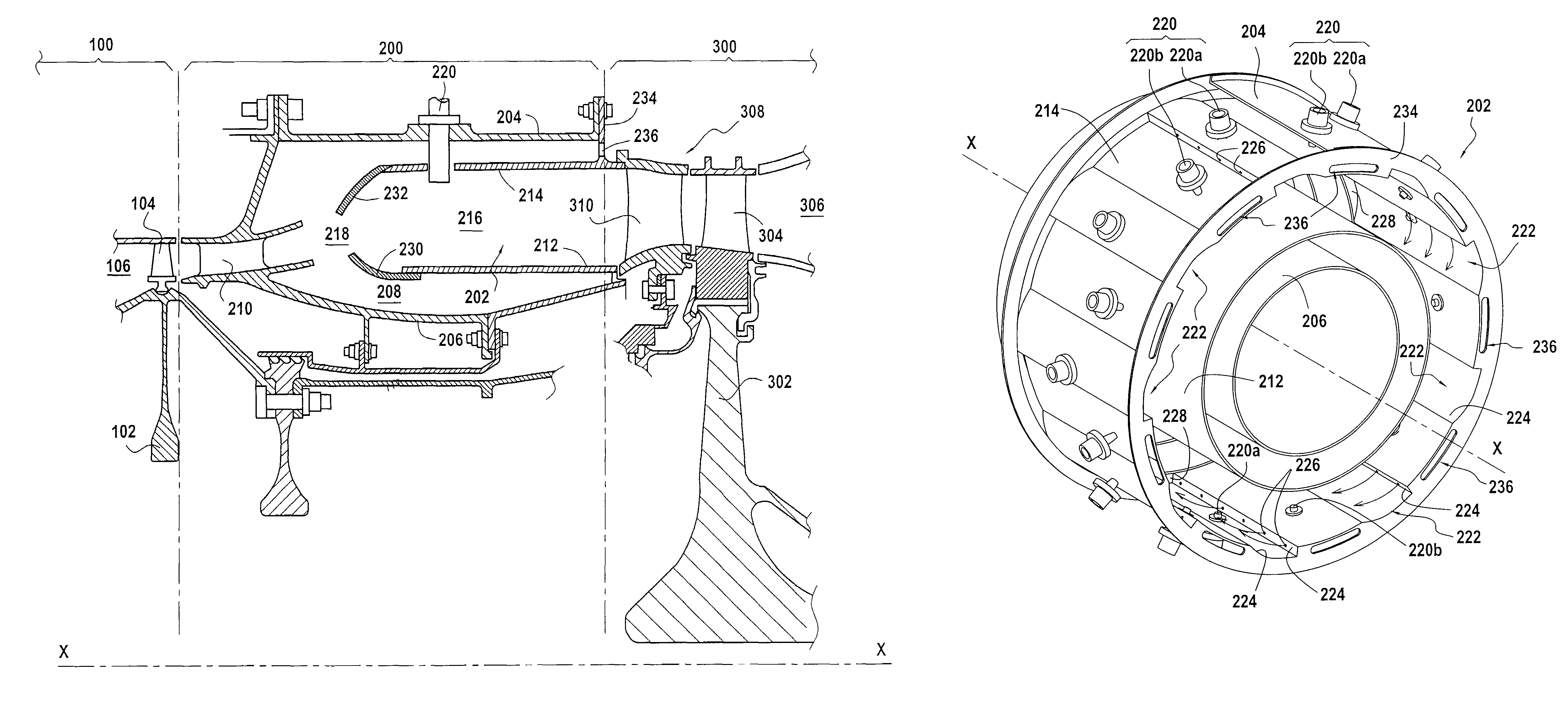
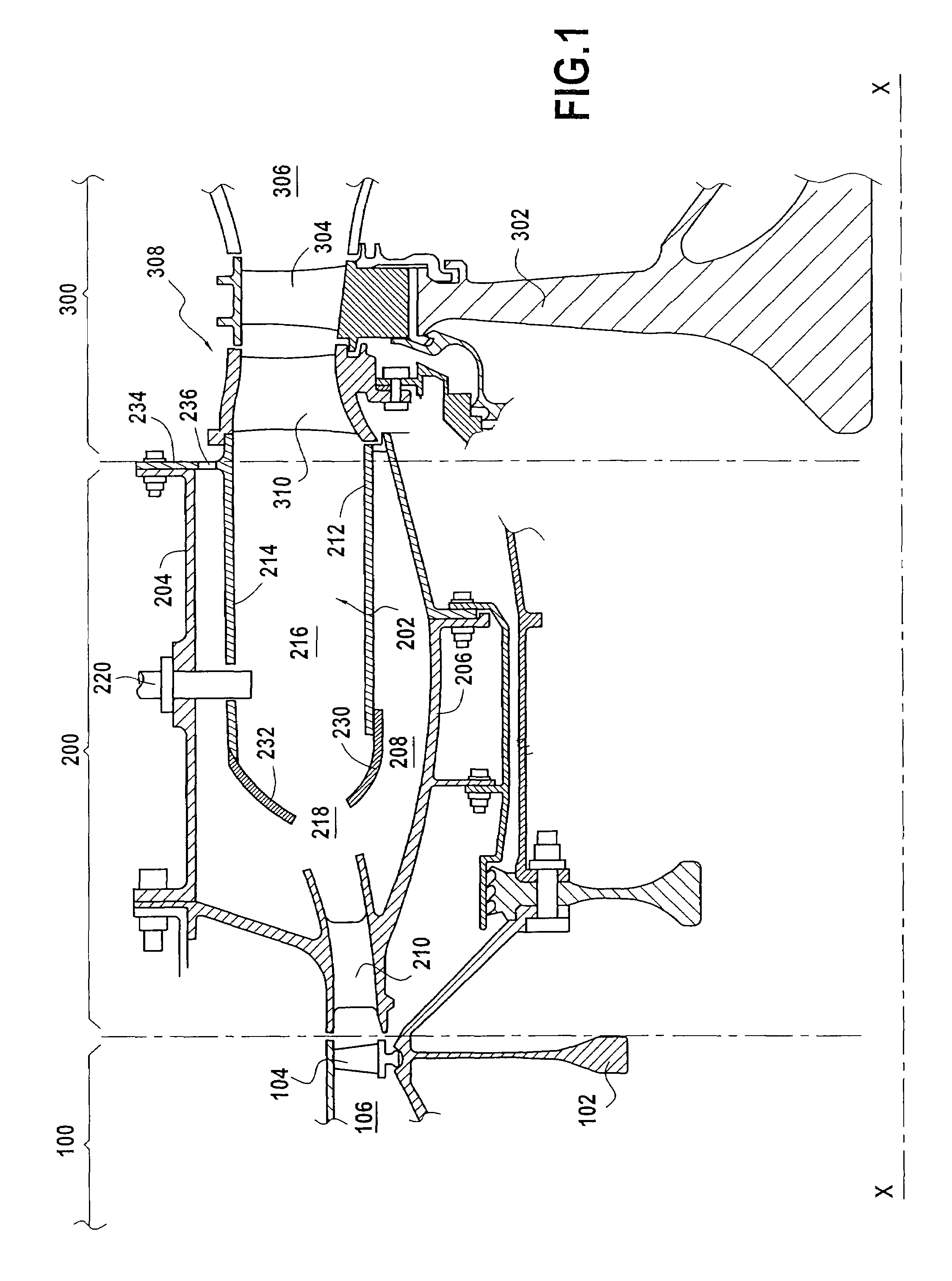
[0029]The turbomachine shown in part in FIG. 1 has a longitudinal axis X-X. Along this axis, it comprises in particular: an annular compression section 100; an annular combustion section 200 disposed at the outlet from the compression section 100 in the flow direction of the air passing through the turbomachine; and an annular turbine section 300 disposed at the outlet from the combustion section 200. Air injected into the turbomachine thus passes in succession through the compression section 100, then the combustion section 200, and finally the turbine section 3.

[0030]The compression section 100 is in the form of a plurality of rotor wheels 102 each carrying blades 104 (only the last stage of the compression section is shown in FIG. 1). The blades 104 of these stages are disposed in an annular channel 106 through which turbomachine air passes and of section that decreases going from upstream to downstream. Thus, as the air injected into the turbomachine passes through the compressi...


PUM


Abstract

A turbomachine combustion chamber includes an inner annular wall, an outer annular wall surrounding the inner wall so as to co-operate therewith to define an annular space forming a combustion area, a plurality of fuel injector systems including pilot injectors alternating circumferentially with full-throttle injectors, and at least one air admission opening out into the upstream end of the combustion area in a substantially longitudinal direction. The outer wall has a plurality of pilot cavities extending between the two longitudinal ends of the outer wall and extending radially towards thereof, the pilot cavities being fed with air from outside the combustion chamber in a common substantially circumferential direction. Each pilot injector opens out radially into a pilot cavity, and each full-throttle injector opens out radially between two adjacent pilot cavities.

Description

BACKGROUND OF THE INVENTION[0001]The present invention relates to the general field of combustion chambers for an aviation or terrestrial turbomachine.[0002]Typically, an aviation or terrestrial turbomachine comprises an assembly made up in particular of: an annular compression section for compressing the air that passes through the turbomachine; an annular combustion section located at the outlet from the compression section and in which the air coming from the compression section is mixed with fuel in order to be burnt therein; and an annular turbine section disposed at the outlet from the combustion section and having a rotor that is driven in rotation by the gas coming from the combustion section.[0003]The compression section is in the form of a plurality of rotor wheel stages, each carrying blades that are located in an annular channel through which the turbomachine air passes and of section that decreases from upstream to downstream. The combustion section comprises a combusti...

Claims


Application Information

Patent Timeline
Patent Type & Authority Patents(United States)
IPC IPC(8): F02C3/00
CPCF23R3/50
Inventor CAMERIANO, LAURENT BERNARDCAZALENS, MICHEL PIERREDUVAL, SYLVAINLUNEL, ROMAIN NICOLAS
Owner SN DETUDE & DE CONSTR DE MOTEURS DAVIATION S N E C M A
Why Eureka
Try Eureka