
Bicycle pedal

a pedal and bicycle technology, applied in the field of bicycle pedals, can solve the problems of one-piece pedal, changeless shape and color, and needing to replace the whole pedal as a whole, and achieve the effect of reducing the cost of mold making, reducing the consumption of time and reducing the cost of fabrication

Inactive Publication Date: 2010-03-02
COMPONENTS
View PDF6 Cites 4 Cited by
  • Summary
  • Abstract
  • Description
  • Claims
  • Application Information

AI Technical Summary

Benefits of technology

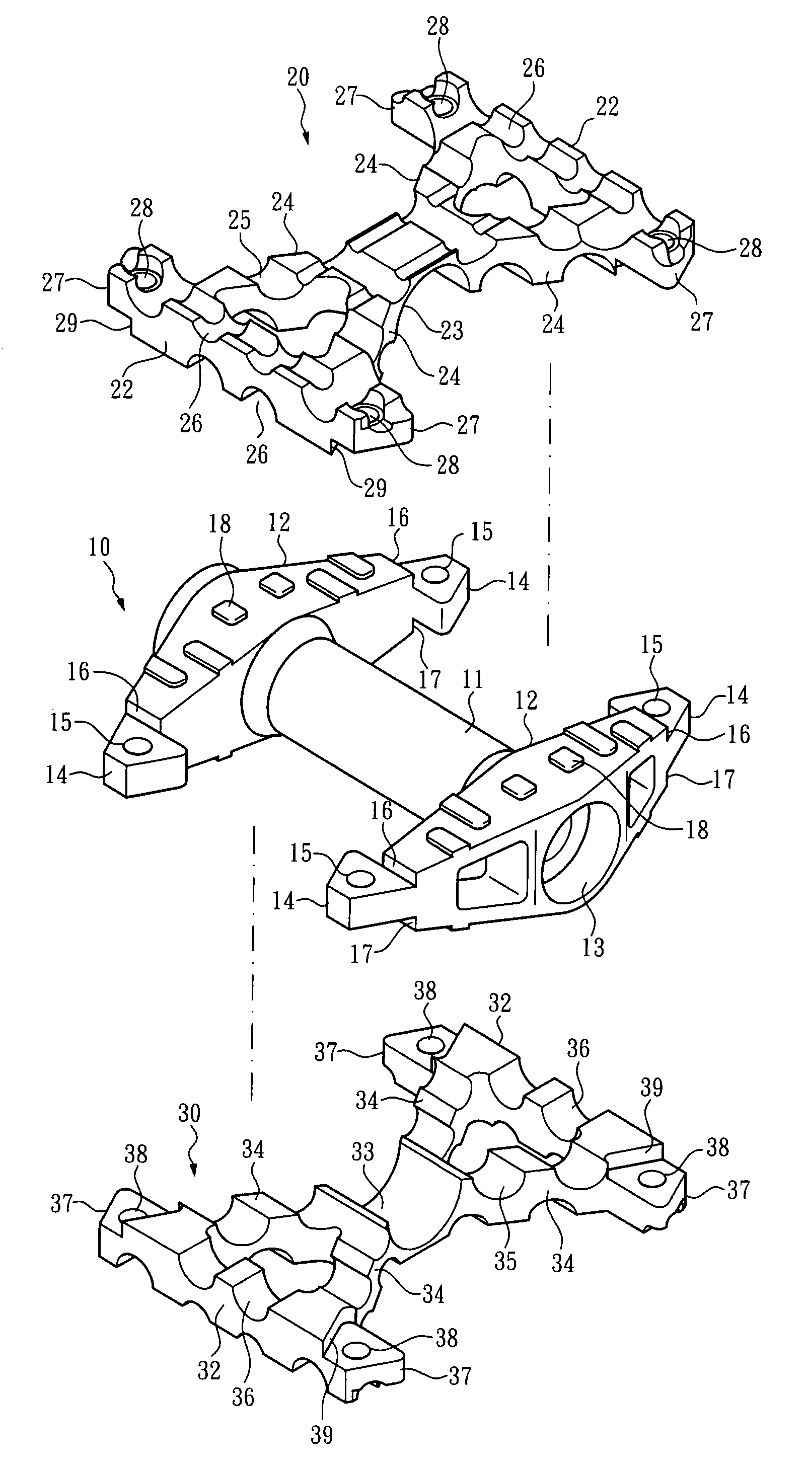
"The present invention is a compromise between a one-piece pedal and a combination pedal. It provides a simplified combination pedal with reduced components and easier fabrication. The central block, upper block, and lower block are all formed in one piece, and they have the same features because they are formed by an identical mold. The central block has an axial bolt tube and two stepping portions. The upper and lower blocks each provide a receiving portion, a plurality of ribs, and two stepping portions. The central block, upper block, and lower block can be combined as a stepping frame by means of a plurality of fastening components. The invention allows for easy replacement of individual components, reducing the need for replacing the entire pedal. The components can also be imparted with different colors during mold forming, showing various color combinations."

Problems solved by technology

However, due to, some technical limitations, such as mold making, forming and mold parting, a conventional one-piece pedal typically has a simple structure and is only capable of providing a simple function of driving a bicycle crank when being pedaled.
However, this may cause some weaknesses of such one-piece pedal, such as the changeless shape and color as well as the plain design.
Moreover, once the one-piece pedal gets partially deformed or damaged, the whole pedal may fail to function and need to be replaced as a whole.
This is somehow uneconomic to a user.
As those combination pedals are typically designed for one or more particular functions, the relatively more complicated shapes, components and fabrication thereof are consequently requisite.
Accordingly, the manufacturing costs and selling prices are relatively higher.
Besides, even though the pedal may be repaired by replacing the damaged components sectionally, it is difficult for a user to replace these components by himself.

Method used


Image

  • Bicycle pedal
  • Bicycle pedal
  • Bicycle pedal

Examples


Embodiment Construction

[0018]In FIGS. 2, 3 and 4, the pedal of the present invention is composed of a central block 10, an upper block 20, a lower block 30 and a plurality of fastening components 40.

[0019]The central block 10 is formed in one piece and comprises an axial bolt tube 11 and two stepping portions 12, each formed around one end of the axial bolt tube 11. The axial bolt tube 11 is hollow and has two bearing recesses 13, each formed at the position corresponding to the center of a respective said stepping portion 12. Each said stepping portion 12 has two fastening portions 14, each shaped as a platform and positioned at one end of the stepping portion 12. Further, each said fastening portions 14 has a fastening hole 15. Since the thickness of the fastening portion 14 is smaller than the thickness of the end of the stepping portion 12, an upper retaining surface 16 and a lower retaining surface 17 are formed at the boundary between the fastening portion 14 and the adjacent stepping portion 12. An...


PUM


Abstract

A bicycle pedal comprises a central block combined with an upper block settled thereon and with a lower block settled thereunder. The central block, the upper block and the lower block are all formed in one piece, respectively. Further, the upper block and the lower block are identical in shape and have the same features because they are formed by means of an identical mold. The central block has an axial bolt tube and two stepping portions. The upper block and the lower block each provides a receiving portion, a plurality of ribs and two stepping portions. Thereby, when the receiving portions engage the axial bolt tube, the stepping portions of the central block, the upper block and the lower block can be combined as a stepping frame by means of a plurality of fastening components.

Description

BACKGROUND OF THE INVENTION[0001]1. Technical Field[0002]The present invention relates to bicycle pedals and, more particularly, to a bicycle pedal having an easily molded and easily fabricated structure.[0003]2. Description of Related Art[0004]FIG. 1 illustrates a conventional one-piece bicycle pedal. The one-piece bicycle pedal comprises a stepping frame and an axial tube traversing the stepping frame through the center thereof. The axial tube is provided for receiving bearings and an axial shaft. Thereby, an external threaded portion formed at one end of the axial shaft can be coupled to an end of a crank of a bicycle. However, due to, some technical limitations, such as mold making, forming and mold parting, a conventional one-piece pedal typically has a simple structure and is only capable of providing a simple function of driving a bicycle crank when being pedaled. However, this may cause some weaknesses of such one-piece pedal, such as the changeless shape and color as well a...

Claims


Application Information

Patent Timeline
Patent Type & Authority Patents(United States)
IPC IPC(8): B62M3/08
CPCB62M3/08Y10T74/2168
Inventor LIN, WEN-HWA
Owner COMPONENTS
Learn More