
Panel type display device

a display device and panel technology, applied in the field of panel type display devices, can solve the problems of deterioration of liquid crystals and increased internal temperature of cases, and achieve the effect of minimizing temperature increas

Active Publication Date: 2010-02-23
SAMSUNG ELECTRONICS CO LTD
View PDF14 Cites 100 Cited by
  • Summary
  • Abstract
  • Description
  • Claims
  • Application Information

AI Technical Summary

Benefits of technology

The present invention is about a panel type display device that can minimize temperature increase in the interior of a case and display panel. The device includes a case, a display panel, at least one circuit board that controls the display panel, and two separate cooling fluid paths. One cooling fluid path cools the display panel, while the other cools the circuit board. The case may have a partition plate that separates the cooling fluid paths, and the display panel and circuit board are mounted between the partition plate and the front or rear surface of the case. The cooling fluid paths may have air inlets and outlets to facilitate air flow. The technical effect of this invention is to provide a more efficient cooling system for panel type display devices, which can prevent overheating and improve their performance and reliability.

Problems solved by technology

For this reason, there is a problem in that the internal temperature of the case is increased due to inter-heating between the display panel and the circuit boards.
In the case of an LCD panel, the temperature increase causes deterioration of the liquid crystal.

Method used


Image

  • Panel type display device
  • Panel type display device
  • Panel type display device

Examples


Embodiment Construction

[0019]Hereinafter, exemplary embodiments of the present invention will be described with reference to the accompanying drawings.

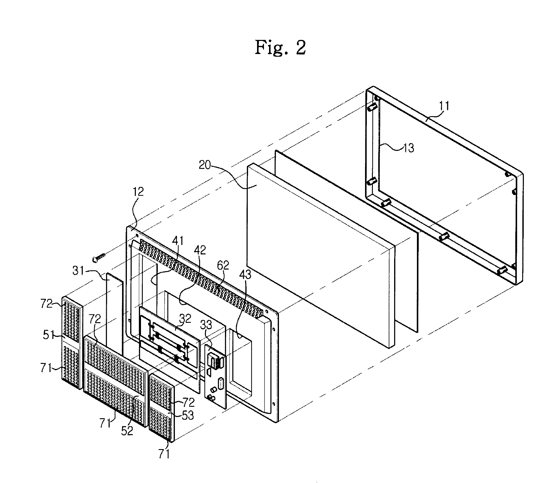
[0020]FIGS. 1 and 2 illustrate a panel type display device according to a first embodiment of the present invention. The display device includes a case 10, a display panel 20 mounted at an inner front of the case 10, and a plurality of circuit boards 31, 32 and 33 mounted at a rear of the case 10.

[0021]The case 10 includes a front case 11 coupled to the display panel 20 at a front thereof and having an opening 13 formed at a screen portion, and a rear case 12 of which an edge portion is coupled to the front case 11 at a rear of the display panel 20.

[0022]The display panel 20 may be an LCD or a PDP. The circuit substrates 31, 32 and 33 are electrically connected to the display panel 20 through a flexible wiring part (not shown). A plurality of electronic components are mounted on the circuit substrates 31, 32 and 33. The plurality of electronic components co...


PUM


Abstract

A panel type display device for minimizing temperature increase in the interior of a case and a display panel. The display device includes a case, a display panel mounted in an interior of the case, at least one circuit board for controlling the display panel, a first cooling fluid path for cooling the display panel, and a second cooling fluid path for cooling the circuit board. In the display device, the first and second cooling fluid paths are separated from each other.

Description

CROSS-REFERENCE TO RELATED APPLICATIONS[0001]This application claims priority from Korean Patent Application No. 10-2007-0002081, filed on Jan. 8, 2007, in the Korean Intellectual Property Office, the disclosure of which is incorporated herein by reference.BACKGROUND OF THE INVENTION[0002]1. Field of the Invention[0003]Apparatuses consistent with the present invention relate generally to a panel type display device and, more particularly, to a panel type display device capable of minimizing temperature increase in the interior of a case and a display panel.[0004]2. Description of the Related Art[0005]A panel type display device, such as a Liquid Crystal Display (LCD) or a Plasma Display Panel (PDP), has a flat type panel on which images are displayed. The panel type display device has a thinner thickness and a lighter weight as compared with those of a conventional cathode ray tube (CRT) display device.[0006]As disclosed in Japanese Patent Unexamined Publication No. 2006-162641, suc...

Claims


Application Information

Patent Timeline
Patent Type & Authority Patents(United States)
IPC IPC(8): H05K7/20H01J17/49
CPCG02F1/133308G02F1/133385H05K7/20963G06F1/20G02F2201/36G09F9/00H04N5/66H04N5/64
Inventor KANG, JOONCHO, JIN HYUNLIM, JEONG SU
Owner SAMSUNG ELECTRONICS CO LTD
Learn More