
Vigilance monitoring technique for vehicle operators

a vehicle operator and monitoring technique technology, applied in the field of vehicle operator monitoring technique, can solve the problems of increased risk of drowsiness detection, increased financial costs as a result of injuries and deaths, and increased risk of accidents

Inactive Publication Date: 2010-02-16
PENN STATE RES FOUND
View PDF11 Cites 63 Cited by
  • Summary
  • Abstract
  • Description
  • Claims
  • Application Information

AI Technical Summary

Benefits of technology

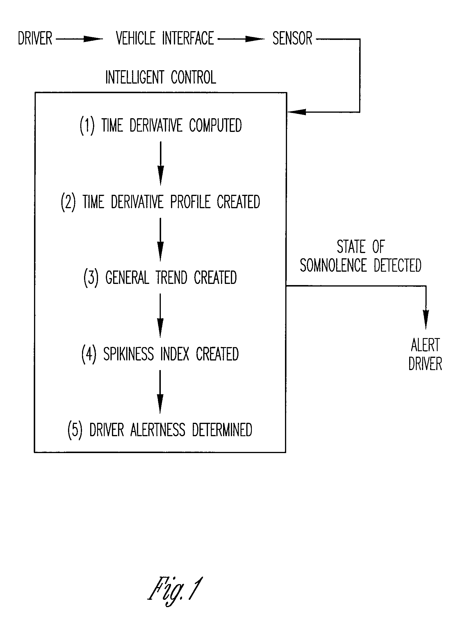
[0006]Therefore it is a primary object, feature and advantage of the present invention to improve over the present state of the art by providing a vigilance monitoring system and method for detecting loss of alertness of a driver independent of the driving environment. Instead of interrogating the driver (physically or graphically) or the vehicle, the present invention interrogates the driver-vehicle interface, such as the steering wheel and the gas pedal. The core component of the invention is the concept of detecting driver / operator alertness by monitoring the magnitude and frequency of the force (and or displacement as in steering wheel rotation or accelerator depression) imparted by a driver at the vehicle interfaces. The time series data of operator imparted displacement or force is then differentiated one or more times to obtain the first, second, third order time derivatives or a time derivative profile. Such time derivatives are substantially independent of the driving environment and are distinctive for determining different levels of driver alertness when compared against a general trend of the time derivative of force or displacement profile.
[0007]It is a still further object, feature or advantage of the present invention to provide a driver vigilance monitor for monitoring driver alertness and / or drowsiness.
[0008]Another object, feature or advantage of the present invention is to provide a driver vigilance monitor wherein a force and / or a displacement sensor is positioned at a driver-vehicle interface, such as the steering wheel, accelerator or brake pedal.
[0009]Still another object, feature or advantage of the present invention is to provide a driver vigilance monitor wherein a force / displacement sensor is installed on both the accelerator, steering wheel and / or brake pedal to increase the probability of drowsiness detection.
[0010]Yet another object, feature or advantage of the present invention is to provide a driver vigilance monitor wherein the sensors monitor a physical characteristic of the driver, such as force or displacement applied by the driver to the driver-vehicle interface.
[0011]A further object, feature or advantage of the present invention is to provide a driver vigilance monitor wherein an intelligent control is operatively connected to the sensor.

Problems solved by technology

Impairment of alertness in vehicle and machinery operators poses a danger not only to themselves but also often to the public at large.
Thousands of deaths and injuries result each year that are fatigue related.
Moreover, the financial costs as a result of the injuries and deaths are prohibitive.
There are several limitations with the existing technologies.
Although the most accurate of the vigilance monitoring techniques, monitoring physiological responses of the body like EEG and ECG, are intrusive, expensive and can distract or cause annoyance to the driver.
Moreover, lane tracking methods require visible lane markings and even if present are significantly impaired by snow, rain, hail, and / or dirt existing on the road.
Nighttime and misty conditions are also impairments.
Image processing techniques used to track eyes and head patterns to track lane maintaining capability necessarily require expensive (both cost and computational requirement-wise) hardware to operate and are highly dependent on factors such as, the relative position of the driver's head with respect to the sensors, illumination, and facial features and / or mental state of the driver, whether happy, anxious, or angry.
Each of these indicators suffers from a relatively low probability of detecting drowsiness.
Many of the measurements for indicating drowsiness do not adequately represent the responsiveness of the driver because of such influences as road conditions, patterns and vehicle type.
Moreover, the cost for these techniques is often prohibitive.
Even yet, more often than not, the existing techniques detect drowsiness when it may be too late for accident prevention purposes.

Method used


Image

  • Vigilance monitoring technique for vehicle operators
  • Vigilance monitoring technique for vehicle operators
  • Vigilance monitoring technique for vehicle operators

Examples


Embodiment Construction

[0063]The present invention relates to a vigilance monitoring system for measuring a driver's level of alertness. That which is disclosed herein is merely exemplary or representative of the present invention. The present invention is not to be limited to the specific disclosure provided herein.

Vigilance Monitoring Technique

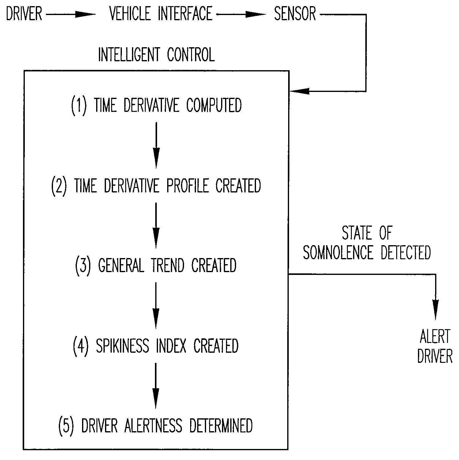
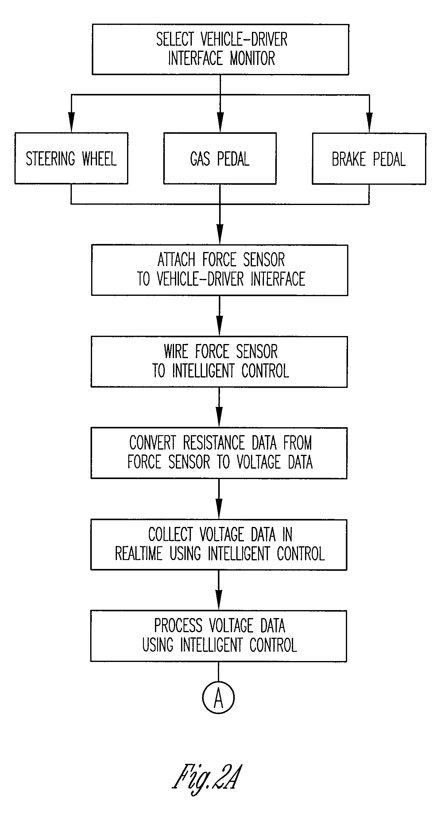
[0064]As shown in FIG. 1, the present driver vigilance monitoring technique monitors the time derivatives of the force and / or displacement profile of the driver's contact with accelerator and / or other driver-vehicle interface, such as the steering wheel and brake to monitor the alertness of the driver. A sensor in the preferable form of a force and / or displacement sensor is attached to the accelerator and steering wheel; the accelerator and steering wheel being the preferred driver-vehicle interfaces to monitor. The force sensor is in form of a thin polymer foil attached to the accelerator pedal, which makes the system non-intrusive to the driver and allows data a...


PUM


Abstract

A vigilance monitoring system to determine the alertness of a driver of a vehicle. The system uses one or multiple sensors located at the driver-vehicle interface (steering wheel, accelerator, brakes). The sensor monitors the magnitude and frequency of the force (or displacement) exerted by a driver at the driver interface. A time derivative of the force or displacement profile is created. The variability of the time derivative of the force / displacement data from the general trend of the data as obtained by an optimized moving average of the data. An intelligent control system measures the variability and compares with an alertness rating scale to determine the alertness score of the driver and issue warning signals and actions as appropriate.

Description

CROSS-REFERENCE TO RELATED APPLICATIONS[0001]This application claims priority under 35 U.S.C. §119 to U.S. Provisional Patent Application No. 60 / 725,822, filed Oct. 12, 2005, herein incorporated by reference in its entirety.BACKGROUND OF THE INVENTION[0002]Impairment of alertness in vehicle and machinery operators poses a danger not only to themselves but also often to the public at large. Thousands of deaths and injuries result each year that are fatigue related. Moreover, the financial costs as a result of the injuries and deaths are prohibitive. As a result, significant efforts have been made in the area of vigilance monitoring of the operator of a vehicle to detect the decrease in attention of the operator and to alert her / him.[0003]Existing driver vigilance monitoring techniques fall within the following broad classes: (1) image acquisition and processing of facial features such as eye and head movements; (2) image acquisition and processing of road lane maintaining capability ...

Claims


Application Information

Patent Timeline
Patent Type & Authority Patents(United States)
IPC IPC(8): G08B23/00
CPCB60K28/066B60W50/14G08B21/06A61B5/7239A61B5/18A61B5/7257B60W40/09B60W2040/0818
Inventor HAQUE, AMANULDESAI, AMIT V.
Owner PENN STATE RES FOUND
Learn More