Eureka AIR delivers breakthrough ideas for toughest innovation challenges, trusted by R&D personnel around the world.

Remote access unit and radio-over-fiber network using same

a technology of radio-over-fiber network and remote access unit, which is applied in the field of wireless communication network, can solve the problems of large propagation loss in the air, significant degraded quality of the second upstream electrical signal, and the effect of reducing the influence of the upstream signal

Inactive Publication Date: 2010-02-09
SAMSUNG ELECTRONICS CO LTD
View PDF5 Cites 14 Cited by
  • Summary
  • Abstract
  • Description
  • Claims
  • Application Information

AI Technical Summary

Benefits of technology

[0022]The system and apparatus of the present invention solve at least the above problems and / or disadvantages and provides at least the advantages below. Accordingly, the present invention provides a remote access unit (RAU) that minimizes the affect on an upstream signal and a radio-over-fiber (RoF) network using the same of a leaked or reflected noise signal based on a downstream signal.

Problems solved by technology

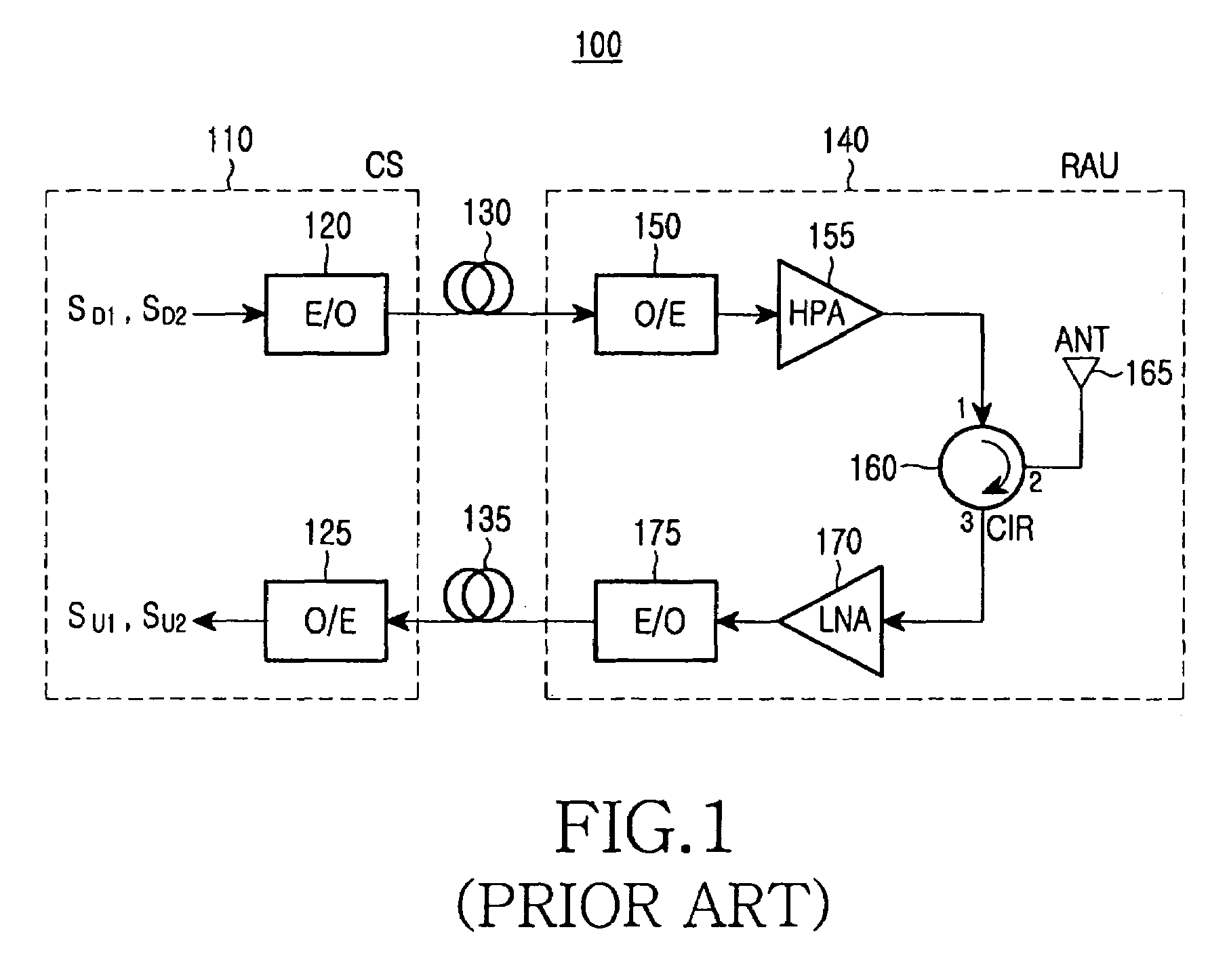
However, the conventional RoF network 100 described above has problems described below.
In addition, since propagation loss in the air is great, power of the first and second upstream electrical signals generated by the antenna 165 are much lower than power of the leaked or reflected noise signal.
Thus, in the above-described cases, quality of the second upstream electrical signal may be significantly degraded.

Method used


Image

  • Remote access unit and radio-over-fiber network using same
  • Remote access unit and radio-over-fiber network using same
  • Remote access unit and radio-over-fiber network using same

Examples


Embodiment Construction

[0034]Now, embodiments of the present invention are described herein below with reference to the accompanying drawings. For the purposes of clarity and simplicity, well-known functions or constructions are not described in detail as they would obscure the invention in unnecessary detail.

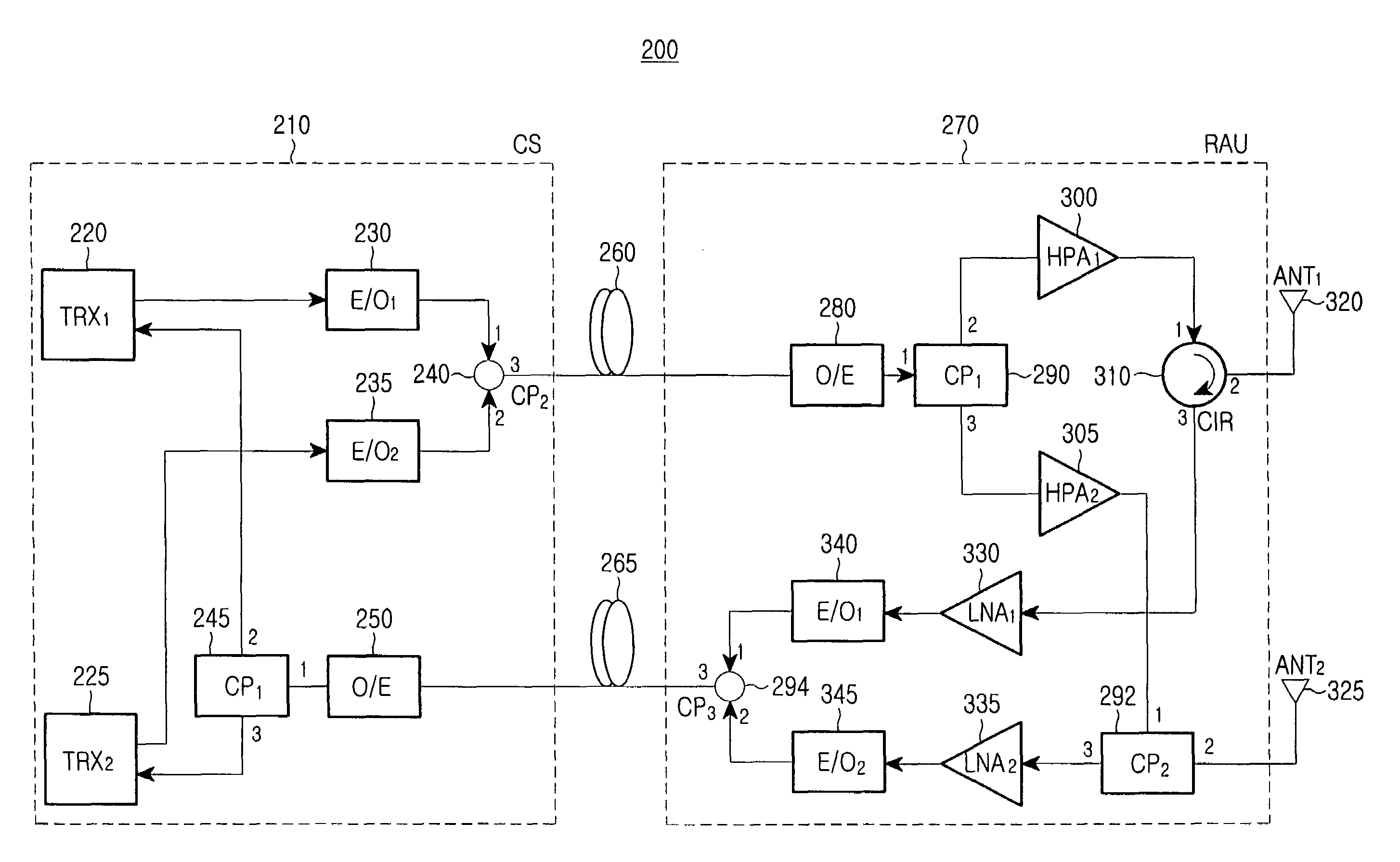
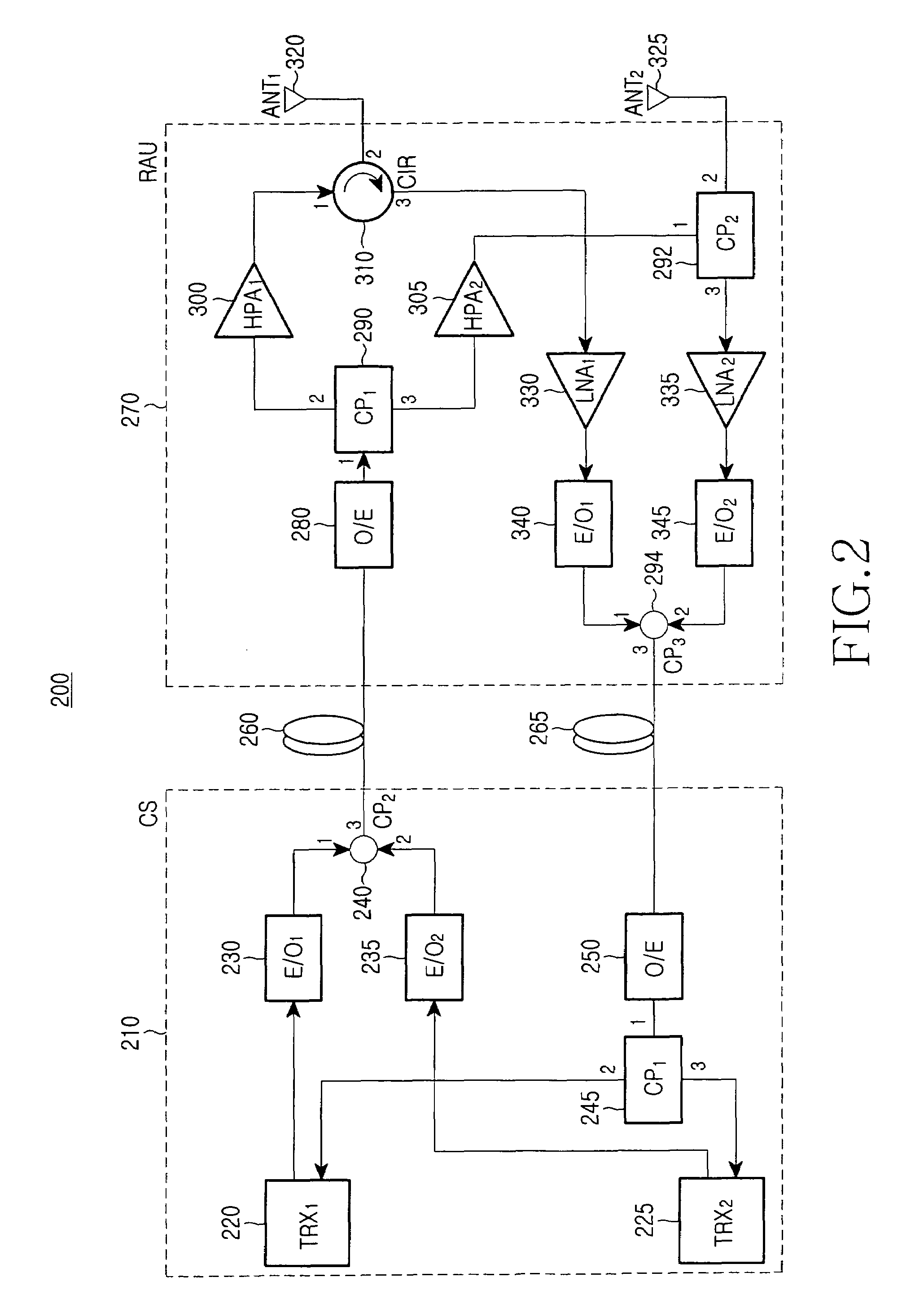
[0035]FIG. 2 is a block diagram of a radio-over-fiber (RoF) network 200 according to a first preferred embodiment of the present invention. Referring to FIG. 2, the RoF network 200 includes a central station (CS) 210 and a remote access unit (RAU) 270 coupled to the CS 210 through first and second optical fibers 260 and 265.

[0036]The CS 210 includes a first transceiver (TRX) 220 for transmitting and receiving electrical signals of a first duplexing method, a second TRX 225 for transmitting and receiving electrical signals of a second duplexing method, a second coupler (CP) 240 for coupling optical signals, first and second electric-to-optical converters (E / Os) 230 and 235, each for converting an elec...


PUM


Abstract

A remote access unit (RAU) apparatus, coupled to a central station (CS) of an RoF network through at least one optical fiber, and which RAU apparatus includes at least one antenna, includes: first and second antenna ports coupled to the at least one antenna; first and second optical fiber ports coupled to the at least one optical fiber; a first coupler for decoupling a first downstream signal of a first duplexing method and a second downstream signal of a second duplexing method, which are input through the first optical fiber port; a circulator for outputting the first downstream signal input from the first coupler to the first antenna port and outputting a first upstream signal of the first duplexing method input from the first antenna port to the second optical fiber port; and a second coupler for outputting the second downstream signal input from the first coupler to the second antenna port and outputting a second upstream signal of the second duplexing method input from the second antenna port to the second optical fiber port.

Description

CLAIM OF PRIORITY[0001]This application claims priority under 35 U.S.C. §119 to an application entitled “Remote Access Unit and Radio-over-Fiber Network Using the Same,” filed in the Korean Intellectual Property Office on Dec. 9, 2005 and assigned Serial No. 2005-120753, the contents of which are incorporated herein by reference.BACKGROUND OF THE INVENTION[0002]1. Field of the Invention[0003]The present invention relates generally to a network for wireless communication, and in particular, to a radio-over-fiber (RoF) network in which a central station (CS) is coupled to at least one remote access unit (RAU) using at least one optical fiber.[0004]2. Description of the Related Art[0005]When various wireless communication services, such as second generation (2G), third generation (3G) wireless local area network (WLAN), and portable Internet are provided in a certain area, a plurality of remote access units (RAUs) for supporting the various wireless communication services and a space f...

Claims


Application Information

Patent Timeline
Patent Type & Authority Patents(United States)
IPC IPC(8): H04B10/24H04J4/00H04M1/00H04B10/2581H04B10/29
CPCH04B10/25758H04B10/2575H04B10/25H04B10/29H04L12/28
Inventor LEE, JAE-HOONHWANG, SEONG-TAEKKIM, BYUNG-JIKLEE, GYU-WOONGKIM, HOONKIM, SANG-HOKIM, YONG-GYOOKIM, SUNG-KEELEE, HAN-LIM
Owner SAMSUNG ELECTRONICS CO LTD
Why Eureka
Eureka Blog
Learn More