
Characterizing achievable flow rates in multi-hop mesh networks with orthogonal channels

a flow rate and orthogonal channel technology, applied in data switching networks, multiplex communication, wireless communication, etc., can solve the problems of limited communication capabilities of wireless nodes and the number of neighbors that these nodes can communicate with simultaneously

Inactive Publication Date: 2010-02-09
ALCATEL-LUCENT USA INC +1
View PDF5 Cites 9 Cited by
  • Summary
  • Abstract
  • Description
  • Claims
  • Application Information

AI Technical Summary

Benefits of technology

"The present invention provides a method and apparatus for routing data from a source node to a destination node in a multi-hop network of nodes interconnected by links. The method involves determining a link-flow vector that satisfies necessary scheduling conditions for achievability, generating a scheduling multi-graph for the network, solving a linear optimization problem over the scheduling conditions to obtain an upper bound on the achievability, and generating a solution comprising a set of routes and an associated schedule for achieving the link-flow vector. The invention addresses the problem of determining achievable rates in wireless networks with sophisticated interference conditions and routing with diversity requirements."

Problems solved by technology

However, in both these network classes, wireless nodes possess limited communication capabilities.
One of these limitations is the number of neighbors that these nodes can communicate with simultaneously.
A problem that arises in wireless multi-hop networks that use orthogonal channels for communication between nodes is characterizing the rates that are achievable.
However, this solution does not address the scenario in which a node is allowed to engage in multiple simultaneous communications with its neighbors, which introduces various system-design and physical-layer constraints.

Method used


Image

  • Characterizing achievable flow rates in multi-hop mesh networks with orthogonal channels
  • Characterizing achievable flow rates in multi-hop mesh networks with orthogonal channels
  • Characterizing achievable flow rates in multi-hop mesh networks with orthogonal channels

Examples


Embodiment Construction

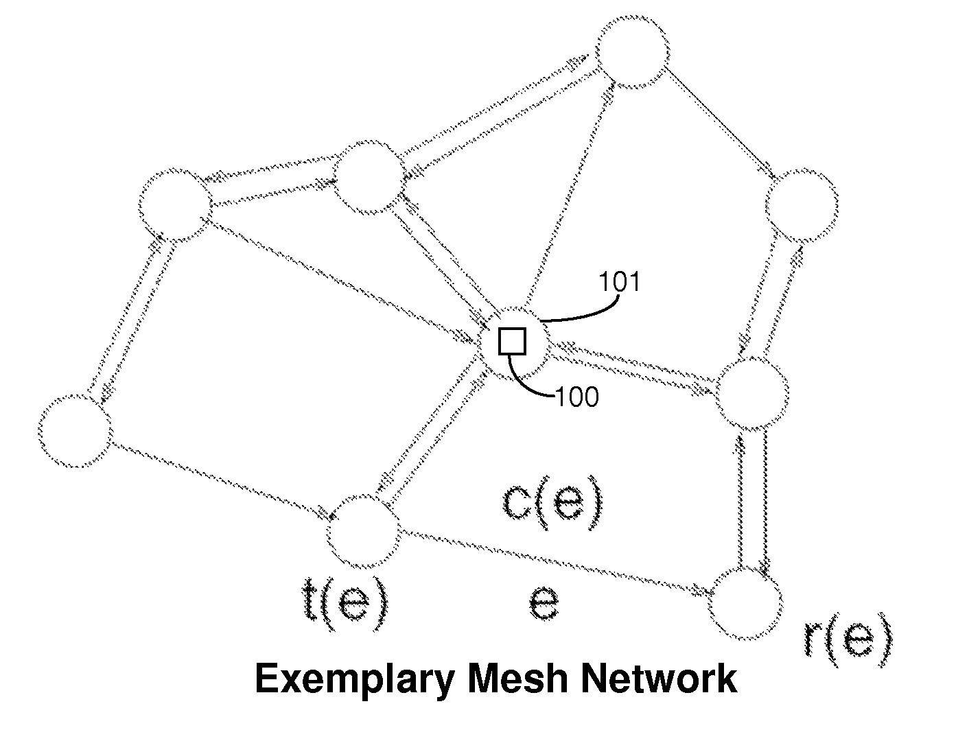
[0025]A node that does not have a duplexer operates in half-duplex mode, i.e., the node can either transmit or receive in each time slot, but cannot both transmit and receive in the same time slot. A node that has a duplexer can operate in full-duplex mode, i.e., the node can transmit and receive in the same time slot. In the context of the present invention, a half-duplex network is one that has only half-duplex nodes, and a full-duplex network is one that has at least one full-duplex node.

[0026]Developments in Code-Division Multiple Access (CDMA) and Multiple-Input, Multiple-Output (MIMO) wireless systems have enabled wireless nodes to engage in simultaneous communication on multiple channels. While, theoretically, nodes can simultaneously transmit and receive using a full-duplex transceiver, as a practical matter, system design constraints might restrict nodes to half-duplex operation. In one embodiment of the present invention, the full-duplex and half-duplex cases are separatel...


PUM


Abstract

A method of routing data in a multi-hop network. In one embodiment, the method includes: determining that a link-flow vector representing a set of flows to be routed from a source to a destination node satisfies necessary scheduling conditions for achievability; generating a scheduling multi-graph having at least one pair of nodes with multiple edges therebetween; deriving one or more sufficient scheduling conditions for achievability of the vector; solving a linear optimization problem over the necessary scheduling conditions to obtain an upper bound on achievability of the vector; and generating, based on the scheduling multi-graph, a routing solution that is a lower bound on the achievability of the vector and has a set of routes and associated schedule for achieving the vector. At least one node v receives transmissions from a specified plurality Ω(v) of other nodes. At least one of the scheduling conditions depends on Ω(v).

Description

BACKGROUND OF THE INVENTION[0001]1. Field of the Invention[0002]The present invention relates to routing in multi-hop (e.g., wireless) mesh networks, and, more particularly, to the routing of flows and scheduling of transmissions to achieve a given rate vector.[0003]2. Description of the Related Art[0004]Wireless multi-hop networks have attracted a lot of attention in recent years as the next evolutionary step for wireless data networks. In multi-hop networks, communication between two end nodes is carried out through a number of intermediate nodes whose function is to relay information from one point to another. In a typical wireless multi-hop mesh network, small nodes that act as simple routers are installed throughout a site (e.g., a home, business, or office) by simply plugging them into power outlets. Each node then transmits a low-power signal capable of reaching neighboring nodes, which in turn transmit to successive nodes, with the process being repeated until the data arriv...

Claims


Application Information

Patent Timeline
Patent Type & Authority Patents(United States)
IPC IPC(8): H04L12/28H04L12/56
CPCH04L47/14H04W40/02H04W8/04
Inventor KODIALAM, MURALIDHARAN S.NANDAGOPAL, THYAGARAJAN
Owner ALCATEL-LUCENT USA INC
Learn More