Optical disk apparatus and information recording/reproduction method

a technology of optical disk and information recording, applied in the field of optical disk apparatus and information recording/reproduction method, can solve the problems of deterioration of reproduction jitter, degraded rf signal quality, and reflected light weakened, so as to achieve high-quality reproduction signal, reduce jitter, and improve reproduction efficiency

Inactive Publication Date: 2010-02-09
PANASONIC CORP
View PDF10 Cites 0 Cited by
  • Summary
  • Abstract
  • Description
  • Claims
  • Application Information

AI Technical Summary

Benefits of technology

[0023]In view of the aforementioned problems, the present invention aims to provide an optical disk apparatus and an information recording / reproduction method which suppress deterioration in the reproduction jitter, error rate, and the like associated with scoop, and which makes it possible to obtain a high-quality reproduced signal.

Problems solved by technology

However, depending on the phase difference between the light emitted from the laser 111 and the reflected light from the optical disk 101, the reflected light may be weakened due to interference with the light emitted from the laser 111.
As a result, the quality of the RF signal is degraded, and the reproduction jitter and error rate are deteriorated.
At this learning, if the laser output power has fluctuations due to scoop, the RF signal obtained from recording marks which are formed in the aforementioned manner cannot be correctly evaluated.
If asymmetry is lost, a write compensation learning: for adjusting for edge shifts at the front end and rear end of a recording mark can no longer be performed accurately, either.
However, according to the method of Japanese Laid-Open Patent Publication No. 2001-189028, the returned light may rather increase in the case where the reflectance of the optical disk is greater than that of the outgoing end face of the laser, thus deteriorating the reproduction jitter and error rate.
Moreover, according to the method of Japanese Laid-Open Patent Publication No. 2001-143299, it is necessary to measure the jitter, and sufficient effects cannot be obtained in the case where the reproduced signal has a poor signal quality.
Such fluctuations in the returned light also cause scoop, whereby the RF signal quality will be degraded and the reproduction jitter and error rate will be deteriorated.

Method used


Image

  • Optical disk apparatus and information recording/reproduction method
  • Optical disk apparatus and information recording/reproduction method
  • Optical disk apparatus and information recording/reproduction method

Examples


first embodiment

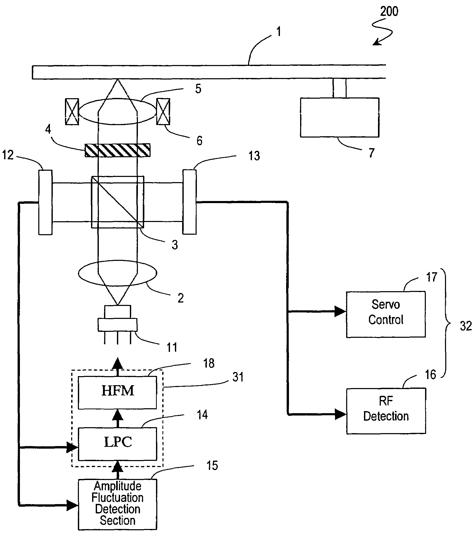
[0057]Hereinafter, a first embodiment of the present invention will be described with reference to the drawings. The present embodiment illustrates an optical disk apparatus which, especially in the presence of a scoop that is in synchronization with an RF signal, suppresses deterioration of the reproduction jitter, error rate, and the like, and provides a high-quality reproduced signal. Compared to a scoop due to other causes, a scoop which, is in synchronization with an RF signal is most influential on the fluctuation or deformation of the waveform of the RF signal.

[0058]FIG. 1 is a block diagram showing the first embodiment of an optical disk apparatus according to the present invention. The optical disk apparatus 200 is suitably used as an optical disk apparatus capable of performing recording or reproduction which supports, in addition to optical disks such as DVD-RAMs and DVD-R / RWs, high-recording-density optical disks for which recording is performed by using laser light in t...

second embodiment

[0088]Hereinafter, a second embodiment of the present invention will be described with reference to the drawings. The present embodiment illustrates an optical disk apparatus which, in the case where there is a scoop that is not in synchronization with the RF signal, suppresses deterioration of the reproduction jitter, error rate, and the like, and provides a high-quality reproduced signal. An example of scoop which is not in synchronization with the RF signal may be, as described earlier, a scoop which occurs due to warpage of an optical disk. If a warped optical disk is subjected to reproduction, the distance between the laser and the recording layer of the optical disk fluctuates, and the phase difference between the returned light and the light emitted from the laser also changes. Therefore, the intensity of the returned light due to light interference changes, and the output power of the laser also fluctuates. FIG. 8 is a block diagram showing a main portion of the second embod...


PUM

PropertyMeasurementUnit
output poweraaaaaaaaaa

Abstract

An optical disk apparatus including: a light source; an objective lens for converging light emitted from the light source toward an optical disk; a first photodetection device for detecting reflected light from the optical disk and outputting a first signal; a signal processing section for receiving the first signal and generating a signal containing information recorded on the optical disk; a second photodetection device for detecting a portion of the light emitted from the light source and outputting a second signal; a light source driving section for receiving the second signal, and based on the second signal, driving the light source so that output power of the light source equals a target value; and an amplitude fluctuation detection section for detecting an amplitude fluctuation amount of the second signal, and if the amplitude fluctuation amount exceeds a predetermined value, changing driving characteristics of the light source driving section.

Description

TECHNICAL FIELD[0001]The present invention relates to an optical disk apparatus and an information recording / reproduction method using an optical disk apparatus.BACKGROUND ART[0002]In recent years, recordable optical disks which allow a large amount of information to be recorded thereon, and optical disk apparatuses which are compatible with them, are becoming prevalent. FIG. 12 schematically shows the structure of a conventional optical disk apparatus which only performs reproduction or a conventional optical disk apparatus which performs recording and reproduction. Since an optical disk apparatus which performs recording is generally also capable of reproduction, an optical disk apparatus which performs recording and reproduction will simply be referred to as an optical disk apparatus which performs recording, in the present specification.[0003]In the conventional optical disk apparatus shown in FIG. 12, light emitted from a laser 111 is converged by a collimating lens 102 so as t...

Claims


Application Information

Patent Timeline
Patent Type & Authority Patents(United States)
IPC IPC(8): G11B7/00G11B7/125G11B7/1263
CPCG11B7/1263G11B7/004
Inventor KAYAMA, HIROSHIMOMOO, KAZUO
Owner PANASONIC CORP
Why Eureka
Try Eureka