
Aircraft flat panel display system

a flat panel display and data display technology, applied in static indicating devices, navigation instruments, instruments, etc., can solve the problems of faa “level a” certification of '558 patents that cannot be easily used in conjunction with rendering controllers manufactured or designed by third party manufacturers or end users

Active Publication Date: 2010-02-09
INNOVATIVE SOLUTIONS & SUPPORT
View PDF9 Cites 4 Cited by
  • Summary
  • Abstract
  • Description
  • Claims
  • Application Information

AI Technical Summary

Benefits of technology

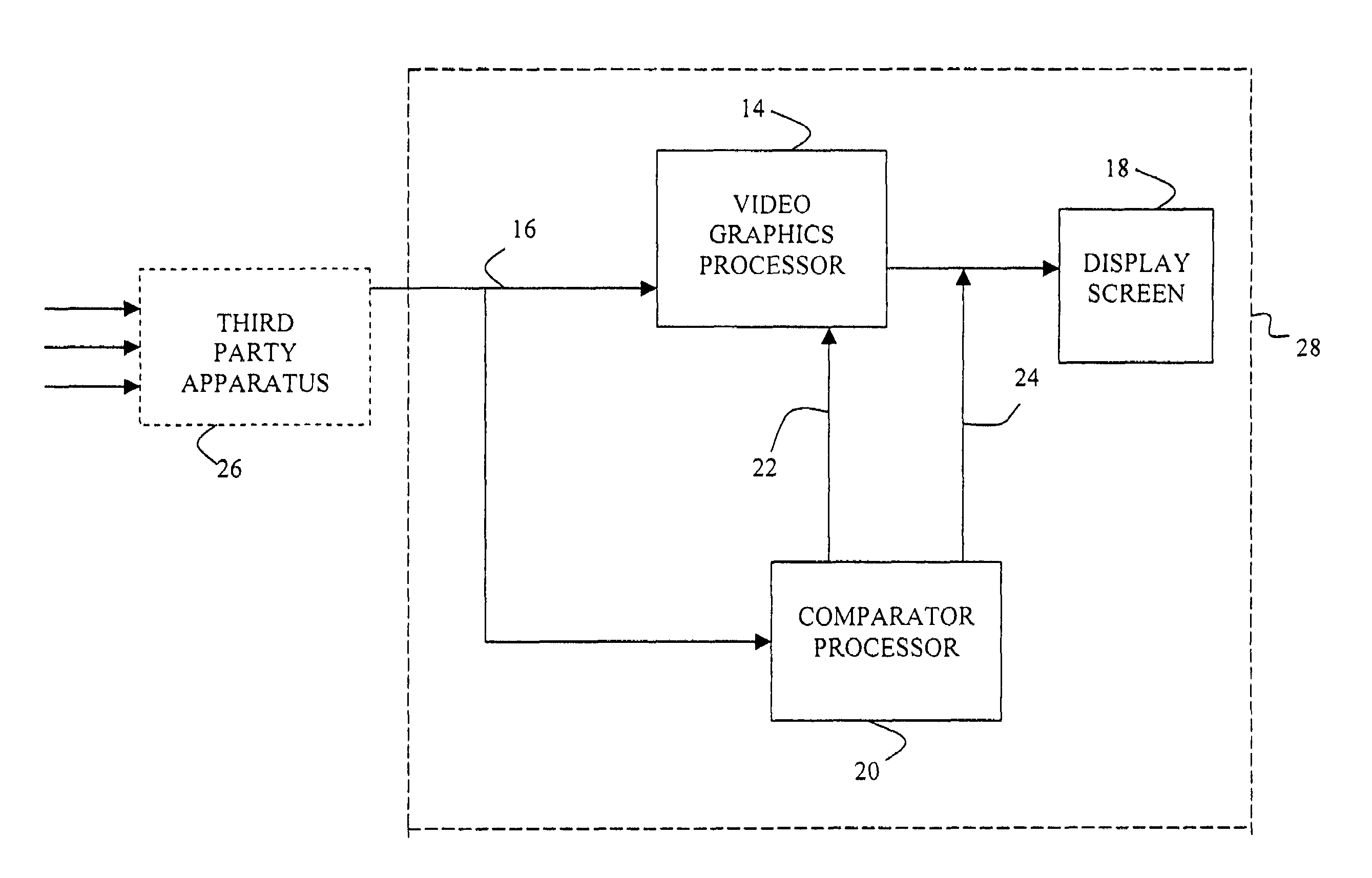
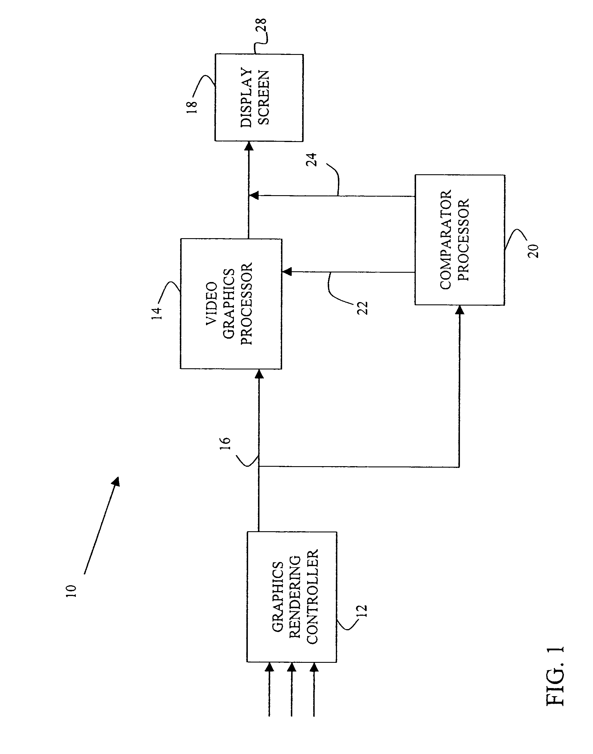
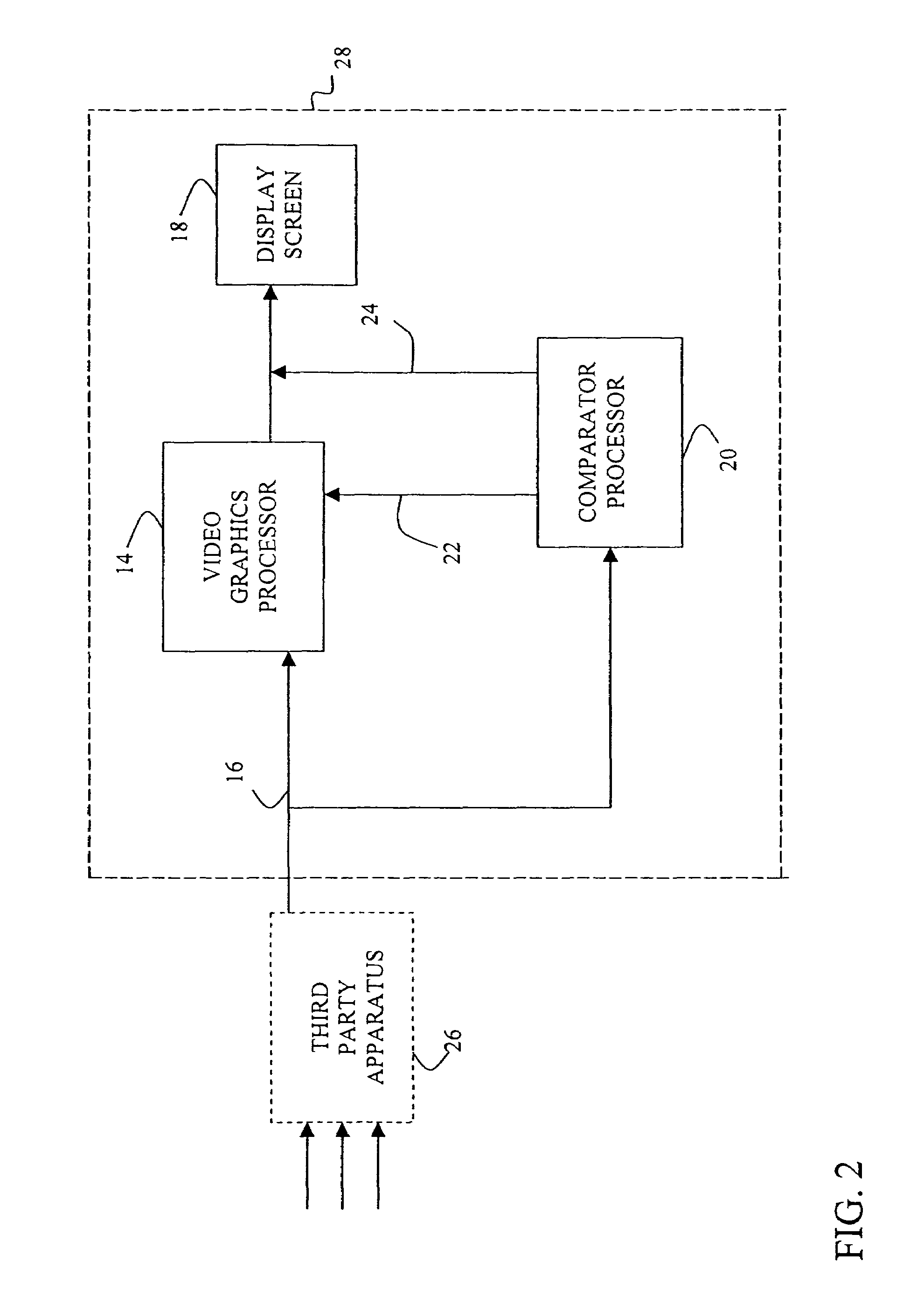
The present invention provides methods and apparatus for ensuring the operating integrity of the graphics rendering engine responsible for generating the graphically-imaged data viewable on an aircraft cockpit flight display without the necessity of foreknowledge of the type of information or the manner or location or format in which the information is depicted on the flight display. This is achieved by providing an improved and display format-independent apparatus, procedures, and criteria for selecting the "points of light" which can be used for effective ongoing verification of the operating accuracy and integrity of the display system components. The invention also allows for the efficient integration and use of the display system with existing third-party devices that provide the aircraft data for presentation to the flight crew by the display system.

Problems solved by technology

The extreme complexity and processing operations required of the rendering processor, on the other hand, make FAA “Level A” certification thereof unusually time consuming and expensive, which seriously inhibits or renders impractical the ability to update or enhance the rendering processor to take advantage of the continuing evolution and advancements in graphics processors and other hardware and software and related technologies if “Level A” certification of the rendering processor is to be maintained.
Similarly, the systems and methods of the '558 Patent cannot easily be employed in conjunction with rendering controllers manufactured or designed by third party manufacturers or end users who are understandably reluctant to expose their often proprietary display rendering software and hardware—at least some detailed knowledge of which would be needed to code or configure the comparator processor for generating the “points of light”—to another who is a likely or potential competitor.

Method used


Image

  • Aircraft flat panel display system
  • Aircraft flat panel display system
  • Aircraft flat panel display system

Examples


Embodiment Construction

[0019]The present invention is primarily directed to aircraft instrumentation display systems which present, on a typically bit-mapped (e.g. liquid crystal or plasma or other flat panel) display formed of a multiplicity of individually-addressable color pixels at locations throughout the display and actuatable to create images on the display, aircraft flight information based on data that is input to the display system for presentation on the display. Such display systems—upon which aircraft flight deck crew members typically rely in piloting and otherwise monitoring and controlling the aircraft and its numerous systems—must operate with extremely high levels of accuracy, integrity and reliability and, as such, are required by FAA regulations to be certified to the most stringent of standards. The invention advantageously expands the range of available hardware, software and technologies that may be used in such high integrity aircraft systems without diminution of the integrity and...


PUM


Abstract

An aircraft cockpit flight deck data display system for displaying, on a viewable display screen, typically anti-aliased graphical imaging data derived from aircraft sensors, generates or receives graphics processing language (GPL) commands that define the information intended for presentation on the display screen. The GPL commands are input to a video graphics processor that is operable to interpret the received GPL commands and to generate therefrom video imaging data transferable to the display screen to populate the screen with the intended information. The same GPL commands are also input to a comparator processor that is operable to interpret the received GPL commands and to generate therefrom selected “points of light”, comprising a limited subset of the video imaging data generated by the video graphics processor. The comparator processor-generated “points of light” are then compared to the respective corresponding video imaging data points generated by the video graphics processor to thereby validate the proper operation of the video graphics processor and the accuracy of the video imaging data generated by the video graphics processor.

Description

RELATED APPLICATION[0001]This application claims priority from U.S. Provisional Patent Application Ser. No. 60 / 700,545, filed Jul. 18, 2005, the entire disclosure of which is expressly incorporated by reference herein.BACKGROUND OF THE INVENTION[0002]1. Field of the Invention[0003]The present invention relates to aircraft cockpit flight deck data display systems and, more particularly, to methods and apparatus for assuring accurate, high integrity rendering of graphically-imaged flight data in an aircraft cockpit display system.[0004]2. Description of the Related Art[0005]U.S. Pat. No. 6,693,558 (“the '558 Patent), the disclosure of which is expressly incorporated by reference herein, describes an aircraft flat panel display system that includes a graphics rendering computer or processor for rendering of anti-aliased graphical imaging data derived from aircraft sensors for full-field imaging on an aircraft cockpit display screen. A comparator processor independently generates, from ...

Claims


Application Information

Patent Timeline
Patent Type & Authority Patents(United States)
IPC IPC(8): G06T1/00G06F15/16
CPCG01C23/005G06F3/1415G09G5/363G06F3/14G09G2320/02G09G2330/12G09G2380/12G06T15/00
Inventor HEDRICK, GEOFFREY S. M.
Owner INNOVATIVE SOLUTIONS & SUPPORT
Learn More