
Variable stiffness support

a support and variable technology, applied in the direction of spring/damper functional characteristics, gearing, hoisting equipment, etc., can solve the problems of system failure, improper function, and reduced life, and achieve the effect of less wear and vibration

Active Publication Date: 2010-01-26
BELL HELICOPTER TEXTRON INC
View PDF16 Cites 13 Cited by
  • Summary
  • Abstract
  • Description
  • Claims
  • Application Information

AI Technical Summary

Benefits of technology

[0015]There is a need for a compact and light weight vibration control device that can effectively change the stiffness at various structural attachments within a dynamic system, so that various natural frequencies within the system can be tuned to prevent adverse resonant conditions in real time.
[0016]Therefore, it is an object of the present invention to provide a compact and light weight vibration control device that can provide a different stiffness at various structural attachments within a dynamic system, thereby providing a simple means for changing the system natural frequencies and responses to applied forces.
[0018]The present invention provides many significant benefits and advantages, including: (1) the ability to tailor the stiffness characteristics of dynamic systems or structures; (2) depending upon the orientation of the device, significant changes in stiffness may be accomplished, thereby providing a wide range of adjustment for various loading conditions; (3) less wear of parts resulting from reduced vibration; (4) it provides a lightweight and simple method for changing the stiffness of a structure at critical points within the structure; (5) the stiffness is continuously variable over the entire range of adjustment, not just at the limits of the components; and (6) the system does not merely balance inertial and spring forces.

Problems solved by technology

In certain situations, these motions can become excessive, causing reduced life, improper function, and possible failure of the system.
This is especially important in regard to aircraft, or more specifically, rotorcraft structures, where failure of the structure may result in loss of life or aircraft.
Excessive vibration within these structures may also lead to discomfort or sickness of passengers or crew, impairing safe operation of the aircraft.
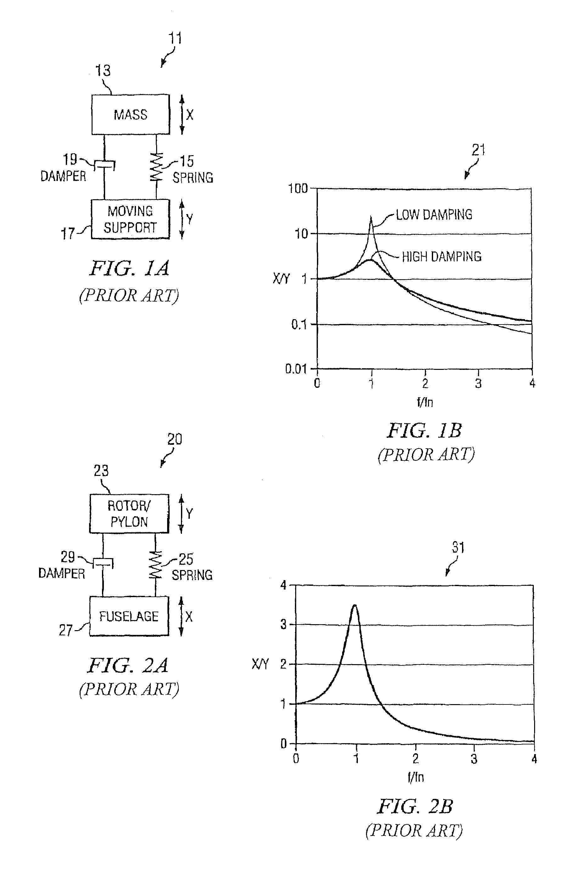
For many systems, such as helicopters, the driving frequency f remains almost constant, i.e., rotor at constant RPM, and sufficient damping is hard to implement without additional weight.
For these systems, multiple driving frequencies from the vibrating rotor combined with the distributed mass and stiffness throughout the airframe create a complex problem in vibration control.
These frequency isolation methods are simple, but cannot be incorporated without adding significant weight to the airframe structure.
In absence of an effective and practical means to change the stiffness of elastic members in dynamic systems, vibration is often controlled by isolating vibrating components.
However, if spring 25 is too soft, excessive deflections can occur as rotor loads change.
These devices, however, are only effective within a narrow frequency band of operation, and may not provide adequate isolation as rotor rpm, flight, or operating conditions change.
The Griffin et al. device is very large and heavy, and difficult or impractical to implement in but a few locations.

Method used


Image

  • Variable stiffness support
  • Variable stiffness support
  • Variable stiffness support

Examples


Embodiment Construction

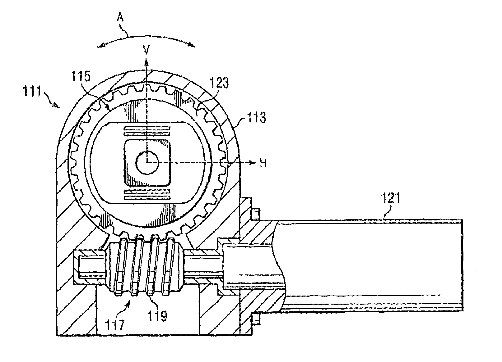
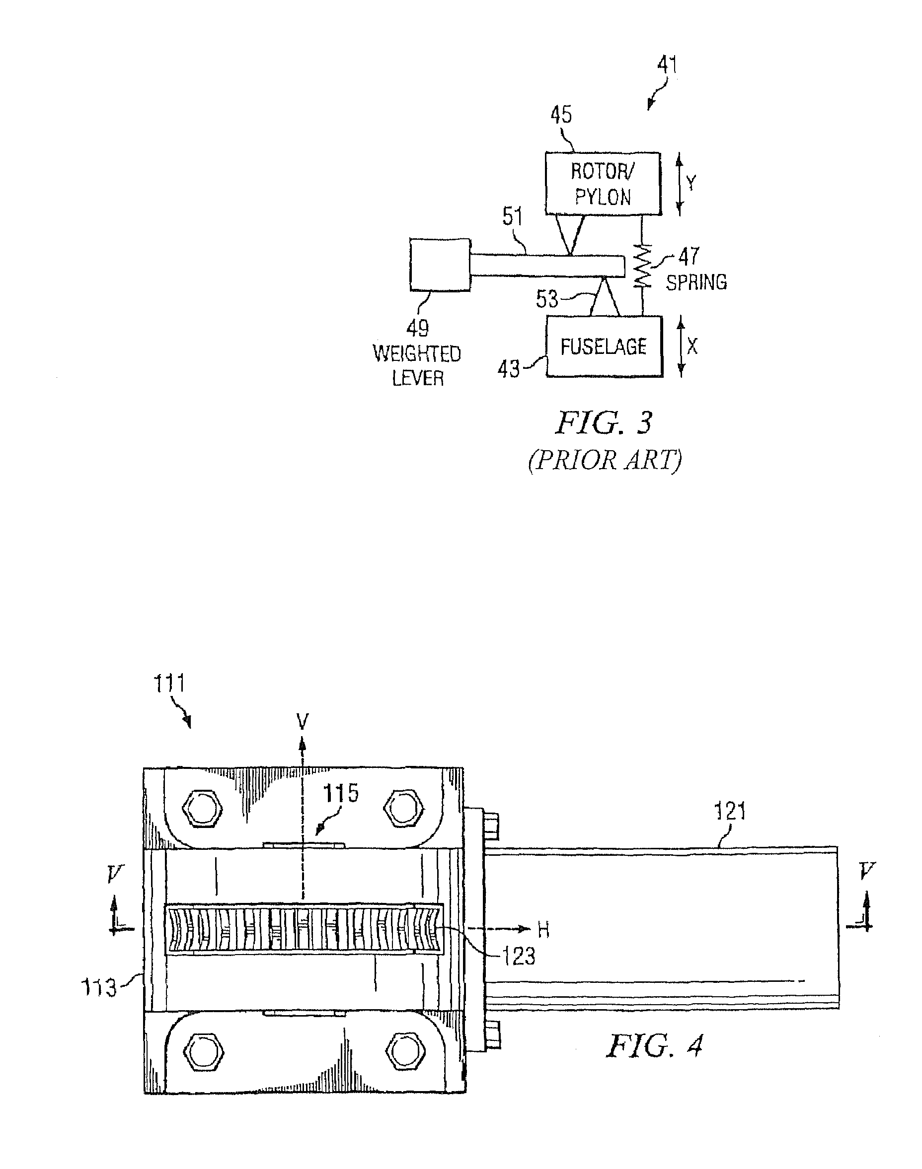
[0031]Referring now to FIGS. 4 and 5 in the drawings, a variable stiffness support 111 according to the present invention is illustrated. Variable stiffness support 111 provides for avoiding resonance by controlling the natural frequency of a system by adjusting the stiffness of the system. Variable stiffness support 111 functions as a variable stiffness spring. Variable stiffness support 111 is configured in such a way as to provide a different stiffness dependent upon the orientation of the elastomer assembly with respect to the direction of an applied load or deflection. When applied to dynamic systems, the present invention provides a simple means for changing the system natural frequencies and responses to applied harmonic forces. This allows selective “tuning” of a system away from resonant conditions, where vibrations and forces are high and potentially destructive. As such, variable stiffness support 111 is particularly well suited to provide variable stiffness at structural...


PUM


Abstract

A variable stiffness support has a support housing that is configured to adjust the orientation of an internal elastomer assembly. The support housing includes an adjustment mechanism, and the elastomer assembly includes an outer ring that encircles an elastomeric material, a central bushing embedded in the elastomeric material, and a plurality of shims embedded in the elastomeric material in a parallel planar fashion.

Description

GOVERNMENT LICENSE RIGHTS[0001]The U.S. Government has a paid-up license in this invention and the right in limited circumstances to require the patent owner to license others on reasonable terms as provided for by the terms of Contract No. DAAH10-00-2-0001.TECHNICAL FIELD[0002]The present invention relates to devices that provide vibration attenuation and isolation at structural joints and attachments.DESCRIPTION OF THE PRIOR ART[0003]Mechanical vibration is a term that describes oscillatory motion resulting from fluctuating forces acting on a dynamic system, that is, a system of mass and elastic elements. In certain situations, these motions can become excessive, causing reduced life, improper function, and possible failure of the system. This is especially important in regard to aircraft, or more specifically, rotorcraft structures, where failure of the structure may result in loss of life or aircraft. Excessive vibration within these structures may also lead to discomfort or sic...

Claims


Application Information

Patent Timeline
Patent Type & Authority Patents(United States)
IPC IPC(8): F16H57/04F16H55/14F16H57/02F16H61/00H02K5/24B64C27/00F16F1/387F16M1/00F16M7/00F16M13/00
CPCB64C27/001F16F1/387B64C2027/002F16F2228/08F16F2230/18Y10T74/18808Y10T74/2184Y10T74/19633Y10T74/19828Y10T74/2186Y10T74/19907
Inventor HAYNES, DAVID F.WILLIAMS, DAVID L.SMITH, MICHAEL R.PASCAL, ROBERT J.
Owner BELL HELICOPTER TEXTRON INC
Learn More