
Strip lighting assembly

a technology of strip lighting and assembly, applied in the direction of lighting and heating apparatus, lighting support devices, furniture parts, etc., can solve the problems that prior proposals have not proved to be particularly commercially successful, and achieve the effect of adjusting the angular position

Inactive Publication Date: 2010-01-19
AMDOR
View PDF10 Cites 88 Cited by
  • Summary
  • Abstract
  • Description
  • Claims
  • Application Information

AI Technical Summary

Problems solved by technology

Although various ways of doing this have been previously proposed, such prior proposals have not proved to be particularly commercially successful.

Method used


Image

  • Strip lighting assembly
  • Strip lighting assembly
  • Strip lighting assembly

Examples


Embodiment Construction

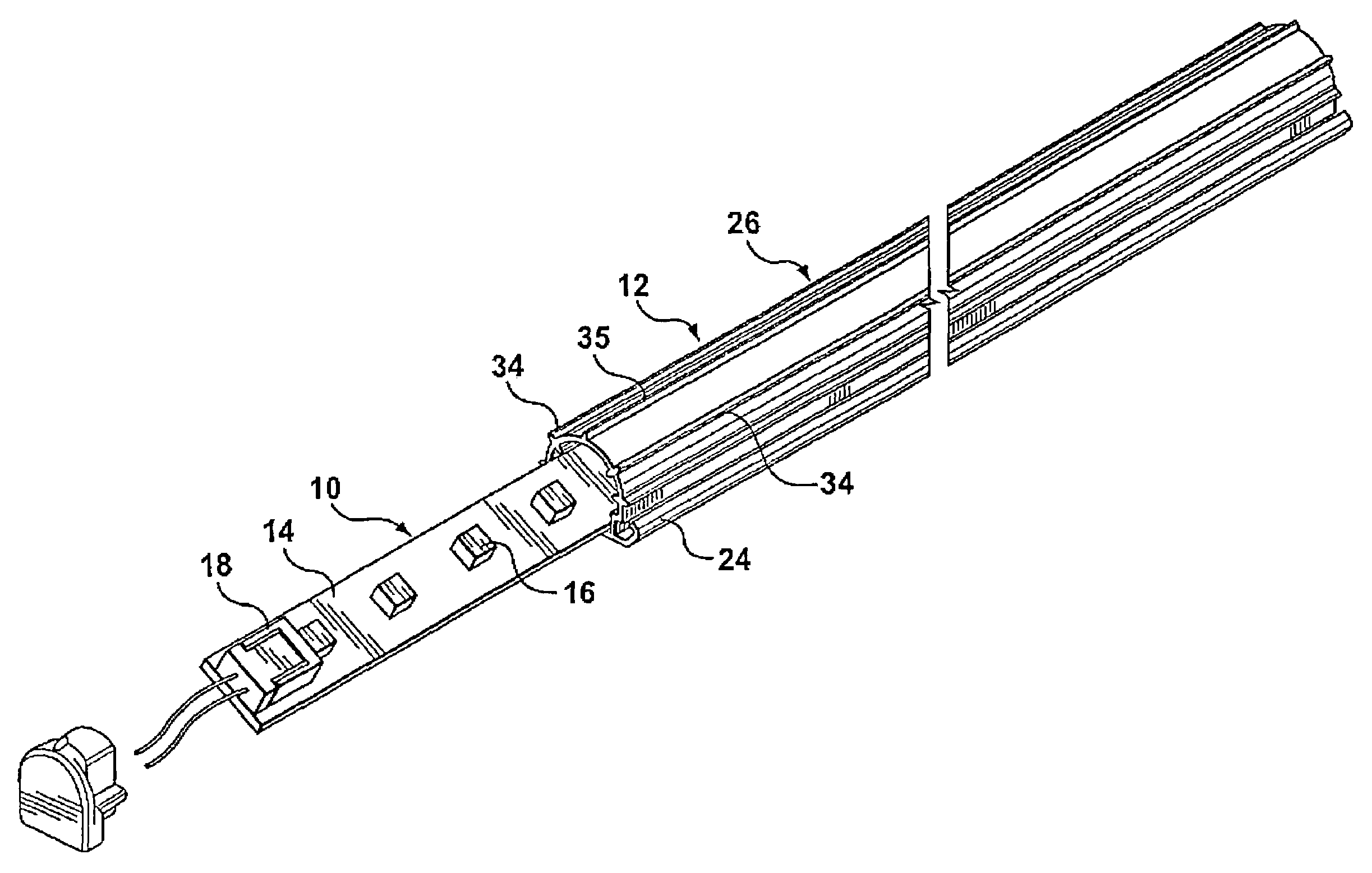
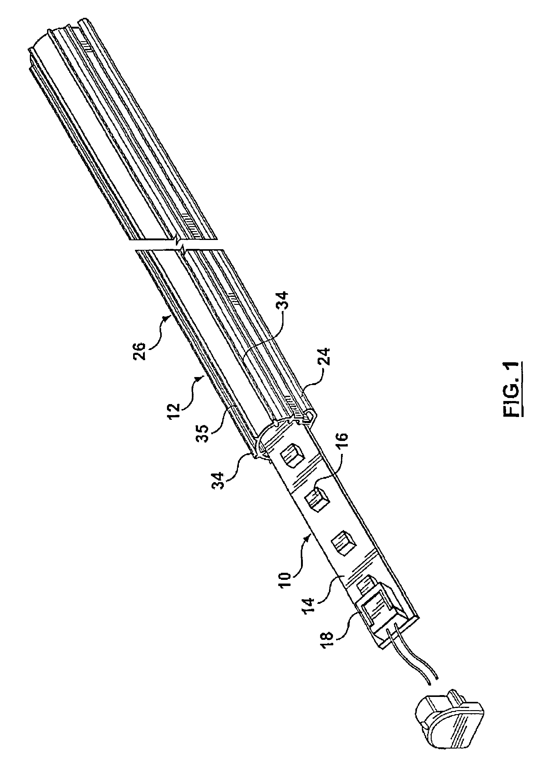
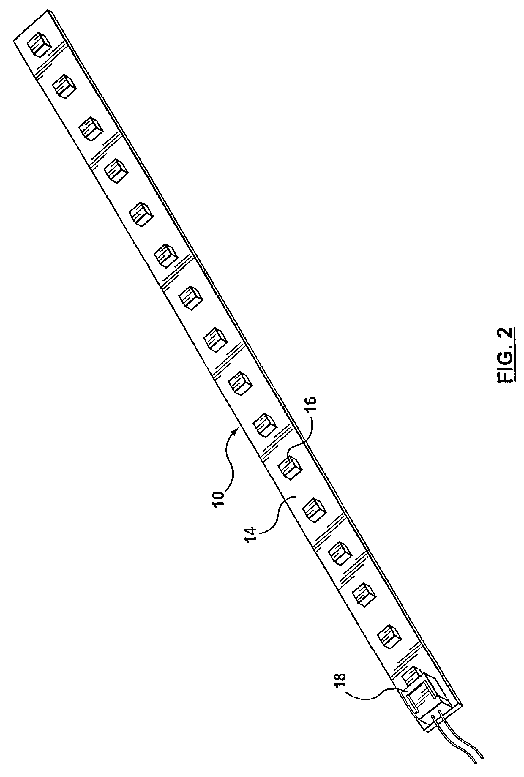
[0018]Referring first to FIGS. 1 and 2 of the accompanying drawings, a strip light assembly comprises an elongated light carrying member 10 and an elongated translucent tubular cover member 12. The light carrying member 10 has an elongated body member 14 with a series of LED lights 16 spaced therealong. The LED lights 16 are electrically connected to an electrical power receiving socket 18 at one end.

[0019]Referring now also to FIGS. 3, 4 and 5, the cover member has a longitudinally extending base portion 20 with upward inclined side portions 22, 24. A cover portion 26 extends upwardly from the central part of the base portion 20. The cover portion 26 has a lower part with a pair of transversely spaced walls 28, 30 and a dome part 32 extending between the side walls 28, 30. The dome part 32 has radially spaced ribs 34 which project inwardly and outwardly. The inwardly projecting parts of the ribs 34 support the light carrying strip member 10 in different angular orientations, as wil...


PUM


Abstract

A strip light assembly including an elongated light carrying member with a series of lights extending along the length thereof, and an elongated translucent tubular cover member in which the light carrying member is removably slidably mounted, the interior of the cover member having radially spaced internal projections positioned to receive the light carrying member therebetween to maintain the light carrying member in selectable different angular orientations in the cover member.

Description

RELATED APPLICATION[0001]This application claims priority from U.S. Provisional Patent Application No. 60 / 800,026 filed May 15, 2006.FIELD OF INVENTION[0002]This invention relates to strip lighting assemblies.BACKGROUND OF THE INVENTION[0003]Strip lighting assemblies are used in many different environments. Sometimes it is desirable to be able to readily adjust the angular orientation of the light produced by a strip lighting assembly. Although various ways of doing this have been previously proposed, such prior proposals have not proved to be particularly commercially successful.[0004]It is therefore an object of this invention to provide a strip lighting assembly with which the angular orientation of the light produced can be readily angularly adjusted.SUMMARY OF THE INVENTION[0005]According to the invention, a strip lighting assembly includes an elongated light carrying member with a series of lights extending along the length thereof, and an elongated translucent tubular cover m...

Claims


Application Information

Patent Timeline
Patent Type & Authority Patents(United States)
IPC IPC(8): F21S4/00F21V33/00
CPCA47B97/00F21V14/02F21V17/005F21V17/02F21V19/0045F21V19/02F21V23/06F21V33/0012F21S4/20F21S4/28F21Y2103/10F21Y2115/10
Inventor WHITEHOUSE, BRUCEJIM, WEBBWONG, TING ON
Owner AMDOR
Learn More