
Beverage bottling plant with a beverage bottle filling machine for filling beverage bottles, and filling elements for the beverage bottle filling machine

a beverage bottling plant and beverage bottle technology, which is applied in the direction of filling using counterpressure, packaging under special atmospheric conditions, packaging, etc., can solve the problems of dirty bottles which must be cleaned or discarded, beverage spillage into and onto the components of filling elements, and waste of beverage products, so as to reduce the effervescence gas in the carbonated beverage, increase the overall cost of operation and increase the frequency of cleaning of the bottling plant machinery

Active Publication Date: 2010-01-19
KHS GMBH
View PDF18 Cites 27 Cited by
  • Summary
  • Abstract
  • Description
  • Claims
  • Application Information

AI Technical Summary

Benefits of technology

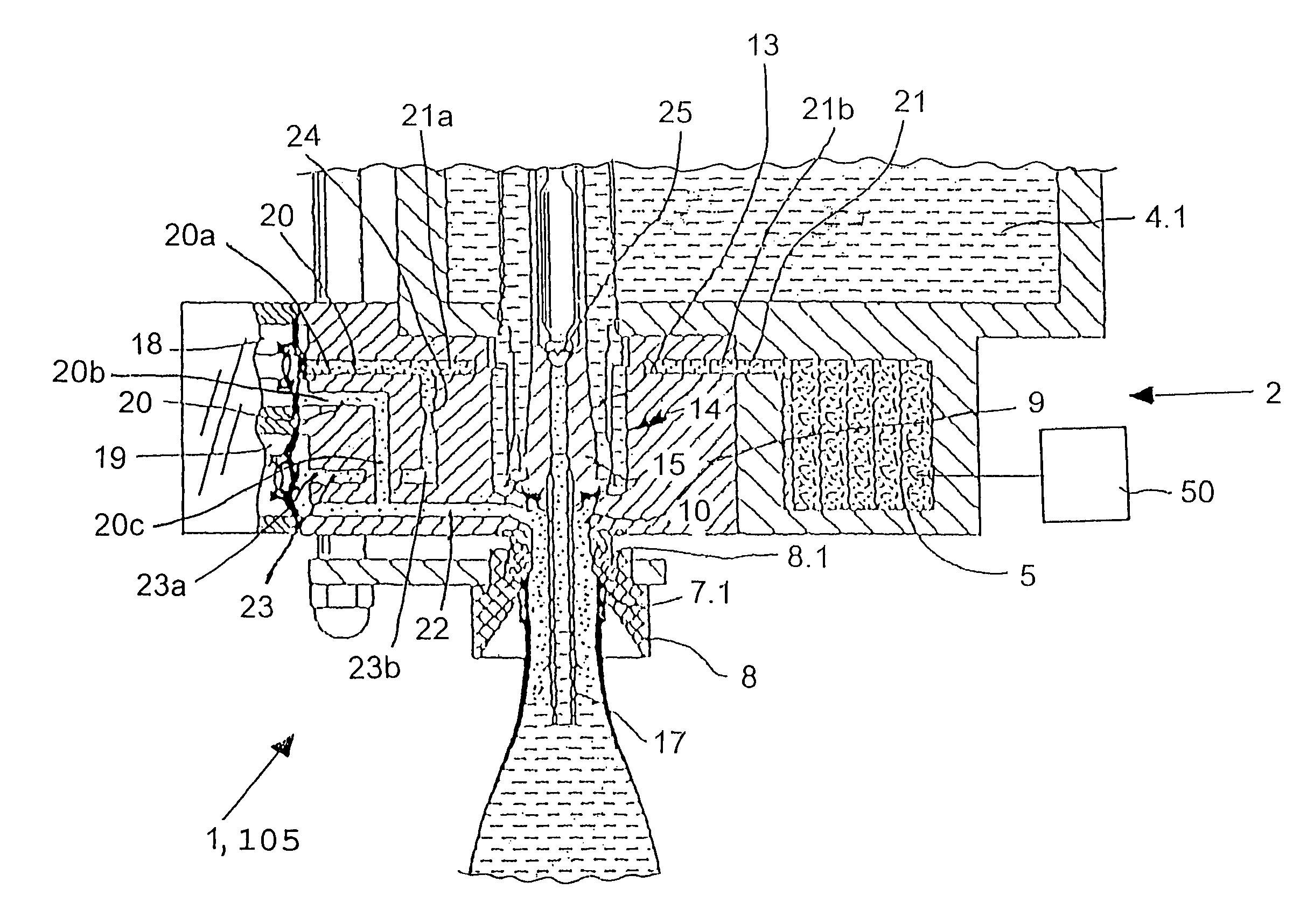
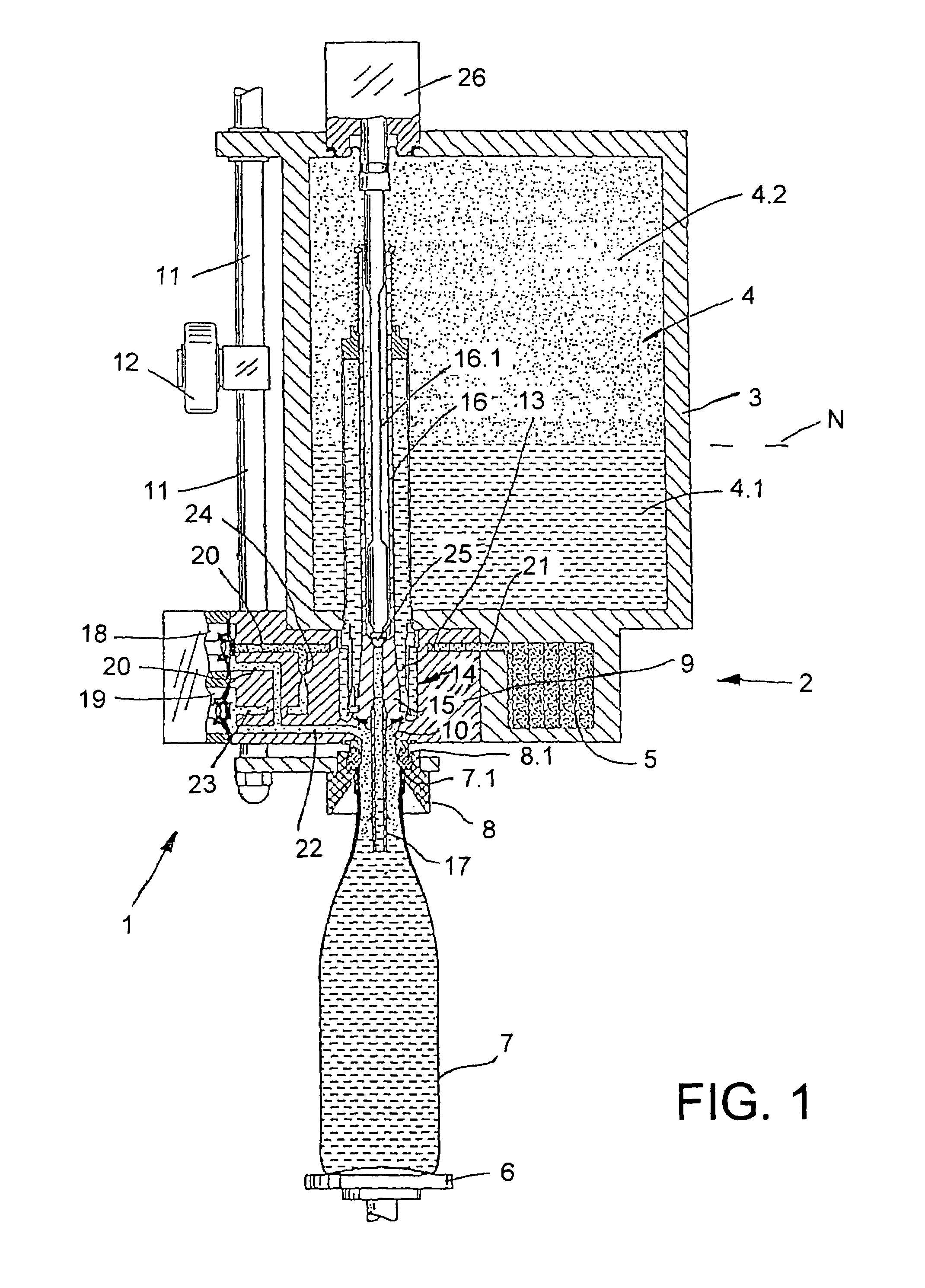
[0006]The object of at least one possible embodiment is to create a filling element for a filling or bottling process that is conducted under counterpressure, and which makes possible a simplified construction of a filling machine while promoting or essentially guaranteeing a high level of operational safety and reliability.SUMMARY
[0009]By controlling the flow of gas by reducing or regulating the flow, the pressure in the container or bottle can be controlled and thus the bubbling up of the effervescing gas in the carbonated beverage can be minimized. If the pressure is not controlled, the carbonated beverage could possibly bubble up quickly and forcefully, thereby resulting in spillage of beverage into and onto the components of the filling elements, and possibly onto the exterior of the bottles and / or the filling machine, and even possibly onto other machinery in the bottling plant or the floor of the plant. Such spillage is clearly undesirable because it results in wasted beverage product and dirty bottles which must be cleaned or discarded. Such spillage also results in increased frequency of cleaning of the bottling plant machinery and components, which increases the overall costs of operating the bottling plant.

Problems solved by technology

If the pressure is not controlled, the carbonated beverage could possibly bubble up quickly and forcefully, thereby resulting in spillage of beverage into and onto the components of the filling elements, and possibly onto the exterior of the bottles and / or the filling machine, and even possibly onto other machinery in the bottling plant or the floor of the plant.
Such spillage is clearly undesirable because it results in wasted beverage product and dirty bottles which must be cleaned or discarded.
Such spillage also results in increased frequency of cleaning of the bottling plant machinery and components, which increases the overall costs of operating the bottling plant.

Method used


Image

  • Beverage bottling plant with a beverage bottle filling machine for filling beverage bottles, and filling elements for the beverage bottle filling machine
  • Beverage bottling plant with a beverage bottle filling machine for filling beverage bottles, and filling elements for the beverage bottle filling machine
  • Beverage bottling plant with a beverage bottle filling machine for filling beverage bottles, and filling elements for the beverage bottle filling machine

Examples


Embodiment Construction

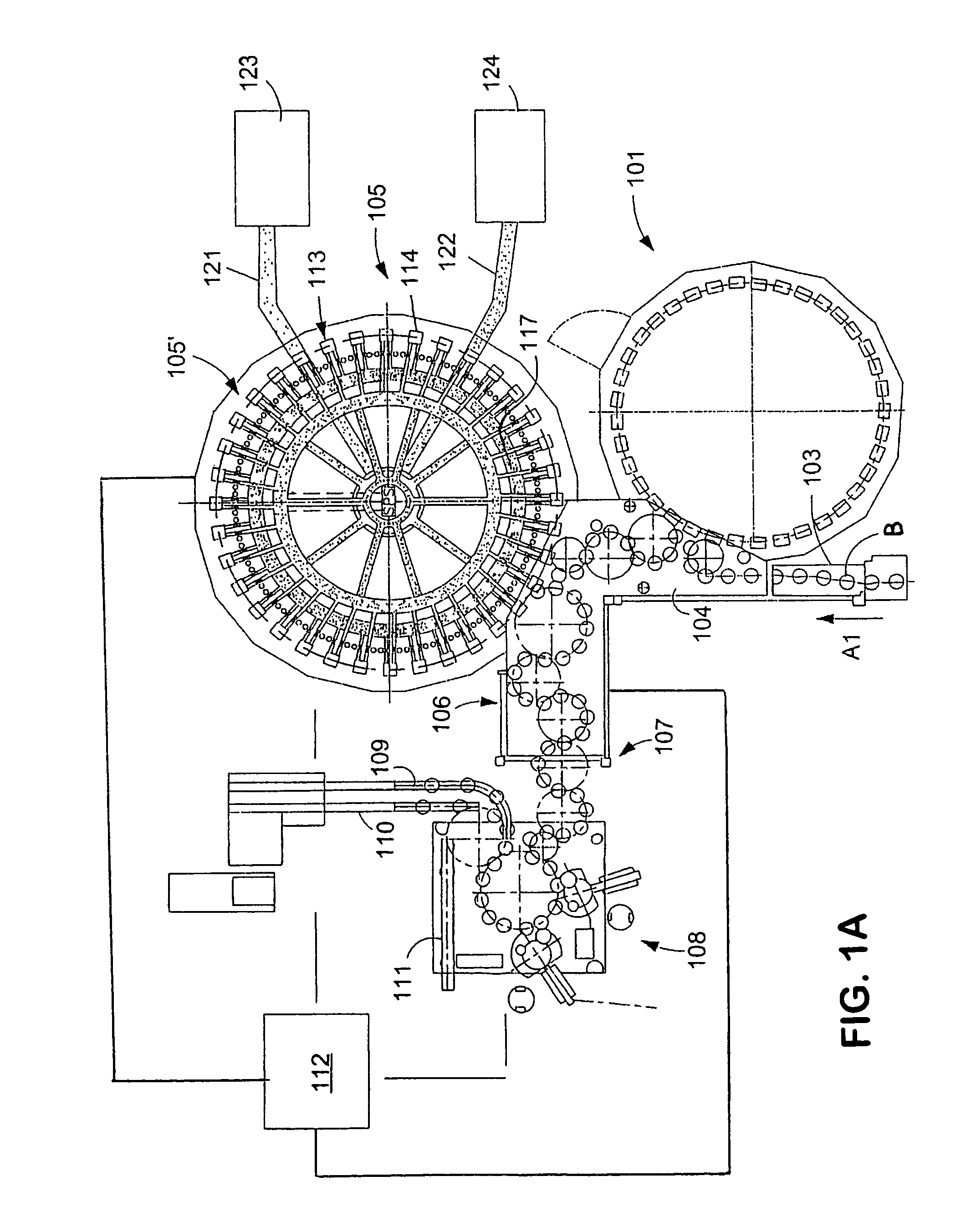
[0018]FIG. 1A shows schematically the main components of one possible embodiment example of a system for filling containers, specifically, a beverage bottling plant for filling bottles B with at least one liquid beverage, in accordance with at least one possible embodiment, in which system or plant could possibly be utilized at least one aspect, or several aspects, of the embodiments disclosed herein.

[0019]FIG. 1A shows a rinsing arrangement or rinsing station 101, to which the containers, namely bottles B, are fed in the direction of travel as indicated by the arrow A1, by a first conveyer arrangement 103, which can be a linear conveyor or a combination of a linear conveyor and a starwheel. Downstream of the rinsing arrangement or rinsing station 101, in the direction of travel as indicated by the arrow A1, the rinsed bottles B are transported to a beverage filling machine 105 by a second conveyer arrangement 104 that is formed, for example, by one or more starwheels that introduce...


PUM


Abstract

A beverage bottling plant with a beverage bottle filling machine for filling beverage bottles, as well as the filling elements for the beverage bottle filling machine.

Description

CONTINUING APPLICATION DATA[0001]This application is a Continuation-In-Part application of International Patent Application No. PCT / EP2004 / 014088, filed on Dec. 10, 2004, which claims priority from Federal Republic of Germany Patent Application No. 103 59 492.2, filed on Dec. 13, 2003. International Patent Application No. PCT / EP2004 / 014088 was pending as of the filing date of this application. The United States was an elected state in International Patent Application No. PCT / EP2004 / 014088.BACKGROUND[0002]1. Technical Field[0003]This application relates to a beverage bottling plant with a beverage bottle filling machine for filling beverage bottles, as well as the filling elements for the beverage bottle filling machine. This application further relates to a filling element for a filling machine for filling a liquid product, such as a beverage, for example, under counterpressure in bottles, cans or similar containers, with a liquid duct that has a controllable liquid valve and ends i...

Claims


Application Information

Patent Timeline
Patent Type & Authority Patents(United States)
IPC IPC(8): B65B31/00B67C3/12
CPCB67C3/12B67C3/2628
Inventor CLUSSERATH, LUDWIG
Owner KHS GMBH
Learn More