
Restoration time in mesh networks

a mesh network and recovery time technology, applied in the field of communication networks, can solve the problems of restricting traffic re-engineering options, less cost-effective routing of grouped demands, etc., and achieve the effect of reducing the worst-case number of cross-connections and reducing the overall restoration tim

Inactive Publication Date: 2010-01-12
ALCATEL-LUCENT USA INC
View PDF136 Cites 1 Cited by
  • Summary
  • Abstract
  • Description
  • Claims
  • Application Information

AI Technical Summary

Benefits of technology

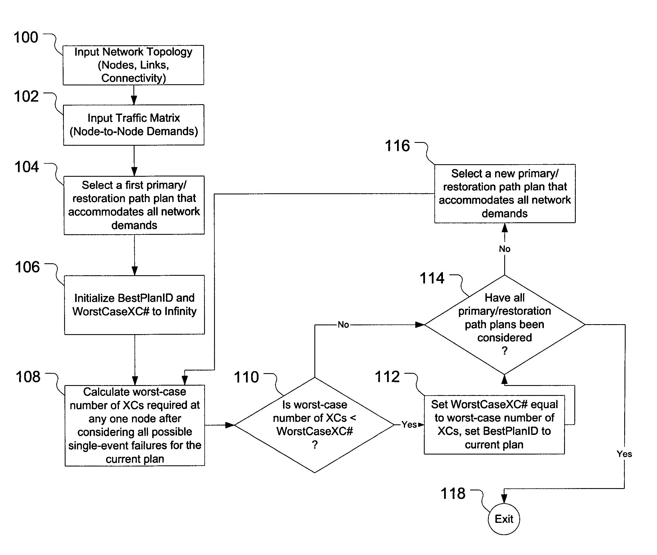
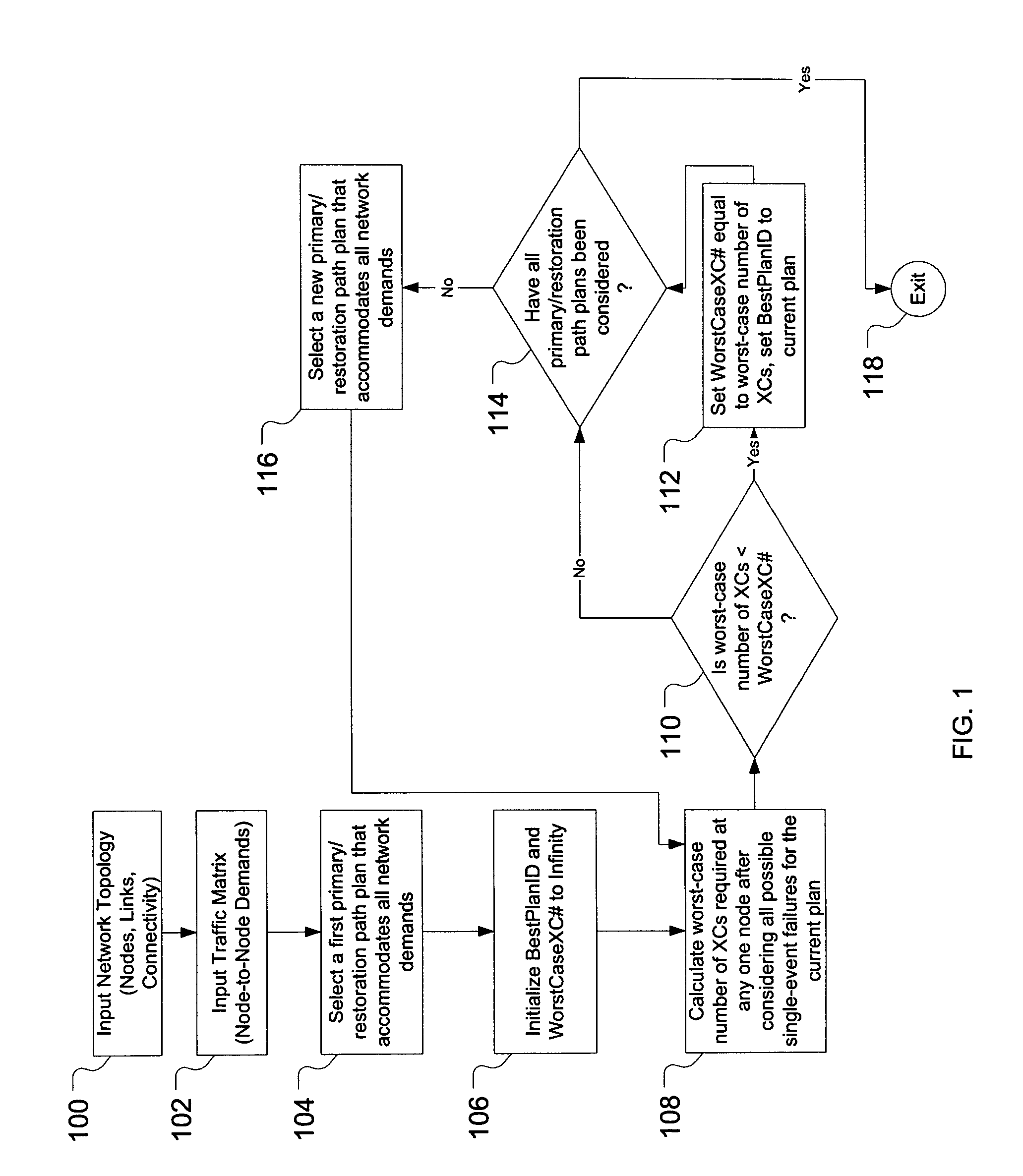
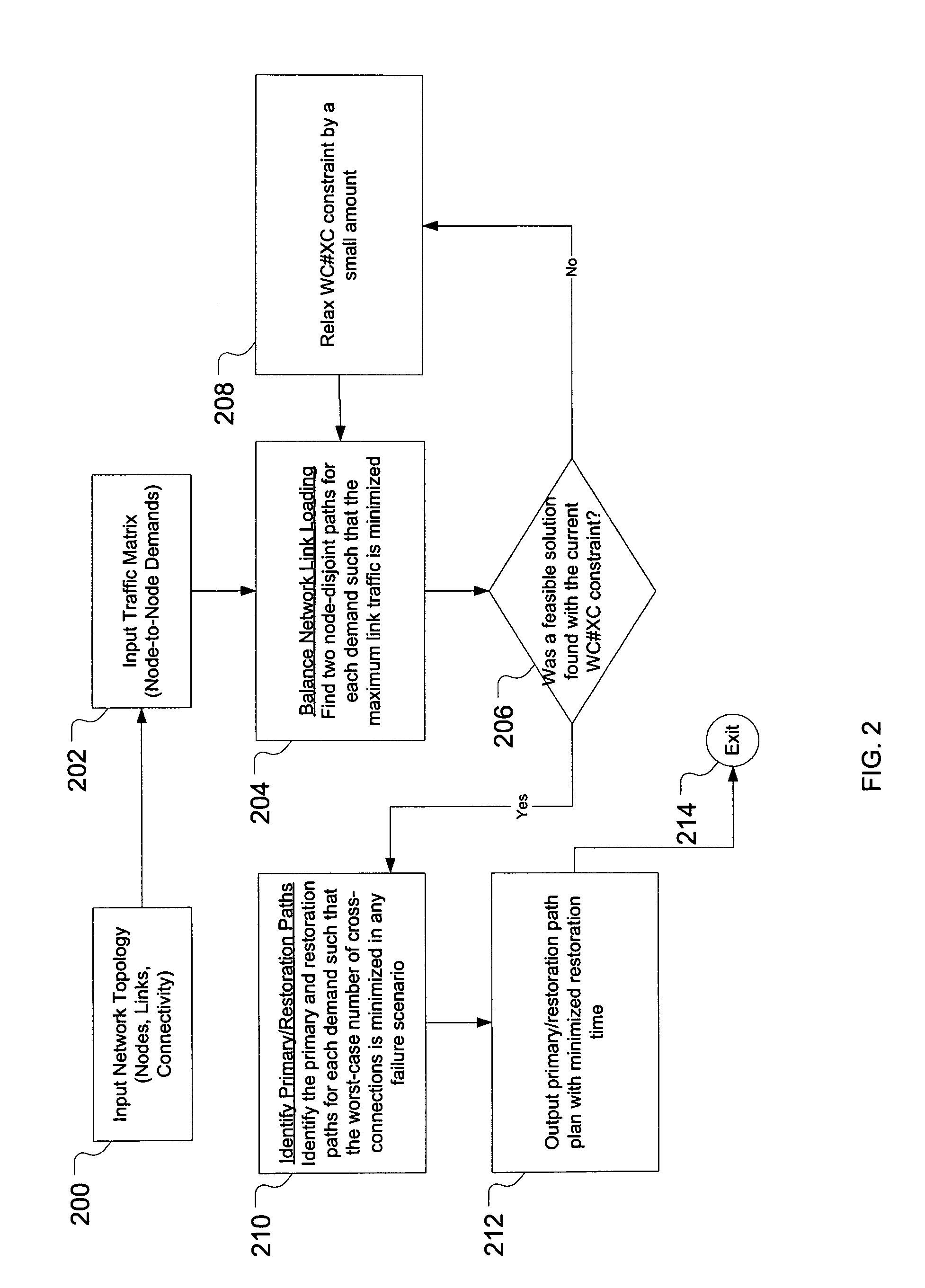
"The present invention provides a method and apparatus for restoration path planning in a mesh network that reduces the worst-case number of cross-connections that must be performed in the event of a single element failure within the network. This results in a significant reduction in the overall restoration time for the network. The invention involves a two-phase optimization process that finds two node-disjoint paths for each service demand within the network to minimize link bandwidth and level the bandwidths within the network. The second phase identifies the primary and restoration paths for each service demand to minimize the worst-case number of cross-connections at any node in the network. The invention also involves service-demand-bundling and node-bundling to route demands along identical paths and minimize cross-connection load. The invention reduces the portion of restoration time associated with failure-related cross-connections in the network."

Problems solved by technology

While signaling can be carried out jointly for the entire group, routing grouped demands is likely to be less cost-effective and also restricts traffic re-engineering options to minimize worst-case cross-connection load.

Method used


Image

  • Restoration time in mesh networks
  • Restoration time in mesh networks
  • Restoration time in mesh networks

Examples


Embodiment Construction

[0018]Reference herein to “one embodiment” or “an embodiment” means that a particular feature, structure, or characteristic described in connection with the embodiment can be included in at least one embodiment of the invention. The appearances of the phrase “in one embodiment” in various places in the specification are not necessarily all referring to the same embodiment, nor are separate or alternative embodiments mutually exclusive of other embodiments.

[0019]Introduction

[0020]Significant research has been done into various restoration and protection strategies for mesh networks at both the service and optical layers. Proposed architectures include centralized vs. distributed, pre-computed vs. computed on demand in real-time, and link-based vs. path-based. Characteristics that distinguish between these various restoration and protection strategies include recovery time, failure coverage, and required recovery capacity. A survey of relevant research as well as a specific distribute...


PUM


Abstract

A restoration path planner that minimizes the worst-case number of cross-connections that must be performed in a network in the event of a single element failure involves a two-phase optimization. The first phase involves finding two node-disjoint paths for each service demand within a network such that the maximum link bandwidth in the network is minimized and the link bandwidths within the network are leveled. The second phase involves identifying the primary and restoration paths for each service demand within the network such that the worst-case number of cross-connections at any node within the network is minimized across all possible single-event failures. Embodiments also consider service demand-bundling that groups service demands with the same source-destination node pairs and routes them along identical primary and restoration paths, and banding, which consolidates multiple low-rate demands into a high-rate demand and consequently decreases cross-connections required in the event of a failure.

Description

CROSS-REFERENCE TO RELATED APPLICATIONS[0001]This application claims the benefit of the filing date of U.S. provisional application No. 60 / 459,163, filed on Mar. 31, 2003.BACKGROUND OF THE INVENTION[0002]1. Field of the Invention[0003]The present invention relates to communications networks and, more specifically, to restoration time improvements in (e.g., optical) mesh networks.[0004]2. Description of the Related Art[0005]In robust communications networks, it is typical to provide path redundancy for services. This is generally done by providing a primary path and a restoration path for each service. In the event of a failure along the primary path, the service traffic is switched over to the restoration path. Note that, in the art, the term “primary path” is often synonymous with the term “working path,” while the term “restoration path” is often synonymous with the terms “protection path” and “alternative path.”[0006]For optical mesh transport networks, a challenge is to provide ...

Claims


Application Information

Patent Timeline
Patent Type & Authority Patents(United States)
IPC IPC(8): G01R31/08H04L12/26H04L12/24
CPCH04L41/0668H04L43/0811
Inventor ALFAKIH, ABDO Y.ATKINSON, GARY W.JANCZEWSKI, CAROL L.MURTI, KAMALANAGARAJAN, RAMESH
Owner ALCATEL-LUCENT USA INC
Learn More