
Method and apparatus for self-contained anesthetic gas reclamation

a self-contained anesthetic gas and gas reclamation technology, which is applied in the direction of lighting and heating apparatus, heating types, separation processes, etc., can solve the problem of rapid decrease in the pressure of the collection chamber, and achieve the effect of recovering the potential energy

Active Publication Date: 2010-01-12
ANESTHETIC GAS RECHAMATION LLC
View PDF100 Cites 10 Cited by
  • Summary
  • Abstract
  • Description
  • Claims
  • Application Information

AI Technical Summary

Benefits of technology

"The patent describes a system and method for removing nitrous oxide and volatile halocarbon gas components from waste anesthetic gases. The system is designed to be minimalistic and easily used in small healthcare facilities, such as dental offices or veterinary clinics. It requires minimal interaction with the healthcare facility's utility systems and can be powered by a small refrigeration unit. The system uses a low-flow scavenging system to collect the waste anesthetic gases, reducing the required capacity of the subsequent waste anesthetic reclamation system. The system also includes a compressor to elevate the pressure of the waste anesthetic gas stream prior to anesthetic recovery by condensation. The compressed waste anesthetic gas is then passed through a multi-stage condenser / heat exchanger to condense and extract the anesthetic gas components. The system is designed to be efficient, flexible, and cost-effective."

Problems solved by technology

If the pressure within the collection chamber exceeds the ambient air pressure, the increased pressure is detected by the pressure sensor, which causes control circuitry to open the exhaust valve and results in a rapid decrease in collection chamber pressure.

Method used


Image

  • Method and apparatus for self-contained anesthetic gas reclamation
  • Method and apparatus for self-contained anesthetic gas reclamation
  • Method and apparatus for self-contained anesthetic gas reclamation

Examples


Embodiment Construction

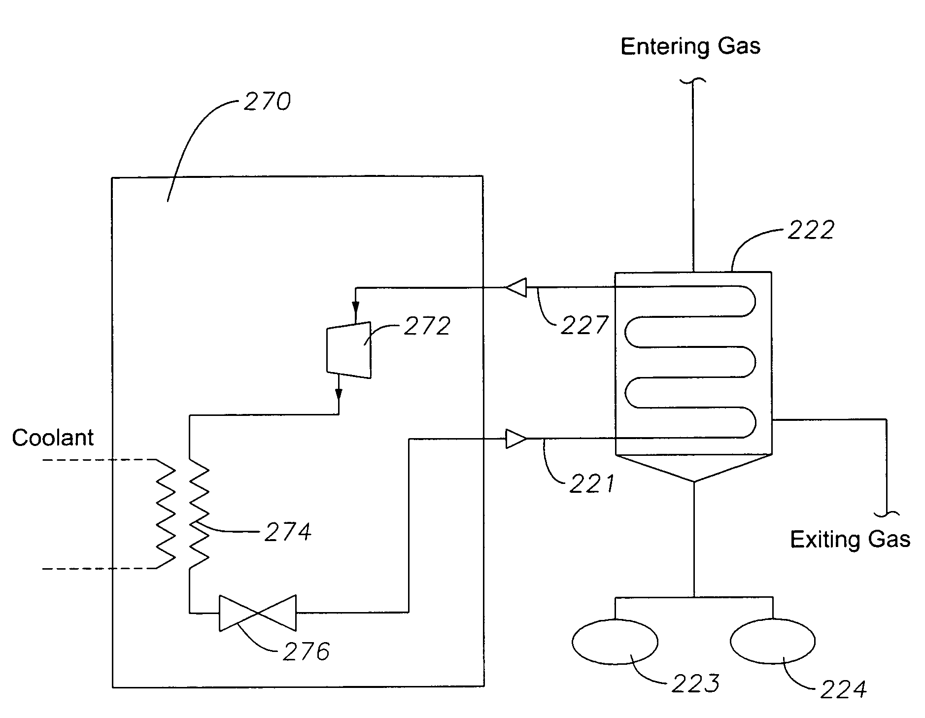
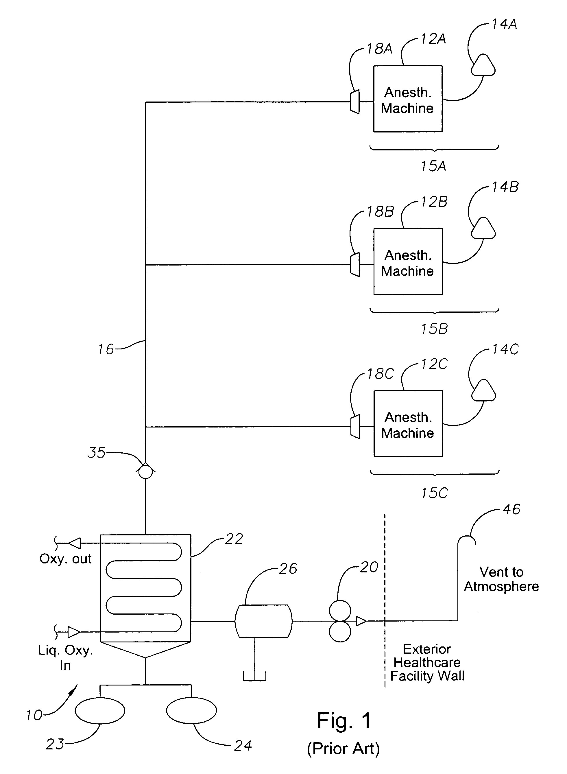
[0043]The waste anesthetic gas reclamation system is arranged and designed to operate with minimal reliance on the utility infrastructure and supplies of a healthcare facility. Unlike other systems which require liquid oxygen and / or liquid nitrogen supplied by the healthcare facility to condense the gaseous anesthetic components, the system disclosed herein requires only the availability of mechanical or electrical power for operation. Moreover, the present system simply needs an atmospheric vent to discharge the waste gases void of their anesthetic components and does not need an extensive waste air handling system. Thus, the preferred embodiment is comparatively self-contained and can be easily accommodated within a physician's office, veterinary clinic, or dental office. Larger, more conventional waste anesthetic gas reclamation systems, such as those traditionally used in hospitals, would be impractical in these settings because of their sheer size and expense.

[0044]FIG. 2 illus...


PUM

PropertyMeasurementUnit
flow rateaaaaaaaaaa
temperatureaaaaaaaaaa

Abstract

A method and apparatus are disclosed for recovering and separating anesthetic gas components from waste anesthetic gases to be purged from a healthcare facility. With minimal reliance on the utility infrastructure and supplies of a healthcare facility, the method and apparatus needs only electrical or mechanical power, a source of waste anesthetic gases, and an atmospheric vent in order to operate. A heat exchanger / condenser, which uses a dedicated heat transfer fluid as a refrigerant, is employed to condense anesthetic gas components from the waste anesthetic gases as either liquid condensates or solid frosts. The warmed heat transfer fluid is cooled in a separate refrigeration unit and recycled back to the heat exchanger / condenser. A preferred embodiment of the invention is a self-contained, packaged unit which can be easily accommodated in a physician's office, small animal clinic, dental office or other healthcare facility requiring effective waste anesthetic gas management.

Description

CROSS REFERENCE TO RELATED APPLICATION[0001]This application is based upon provisional application 60 / 680,644 filed on May 13, 2005, the priority of which is claimed. On Nov. 4, 2005, Applicants filed related non-provisional application Ser. No. 11 / 266,966, which claims the benefit of U.S. provisional patent application 60 / 680,644 filed on May 13, 2005. On May 11,2006, Applicants filed related non-provisional application Ser. No. 11 / 432,152, which claims the benefit of U.S. provisional patent application 60 / 680,644 filed on May 13, 2005. On May 11, 2006, Applicants filed related non-provisional application Ser. No. 11 / 432,189, which claims the benefit of U.S. provisional patent applications 60 / 680,644 filed on May 13, 2005 and 60 / 682,249 filed on May 18, 2005.BACKGROUND OF THE INVENTION[0002]1. Field of the Invention[0003]This invention concerns the treatment of waste anesthetic gases produced by one or more anesthesia delivery systems of a healthcare or other facility that use inha...

Claims


Application Information

Patent Timeline
Patent Type & Authority Patents(United States)
IPC IPC(8): F25J3/00B01D9/04F24F5/00
CPCA61M16/009A61M16/0093A61M2205/3606A61M2202/0208A61M2202/03A61M2202/0007
Inventor BERRY, JAMES M.MORRIS, STEVE
Owner ANESTHETIC GAS RECHAMATION LLC
Learn More