Eureka AIR delivers breakthrough ideas for toughest innovation challenges, trusted by R&D personnel around the world.

Spread spectrum signal detection with inhibiting for known sidelobe locations

a technology of spreading spectrum signal and inhibiting, which is applied in the direction of transmission, electrical equipment, etc., can solve the problems of limited code length, many systems using non-ideal codes, and it is difficult to distinguish a sidelobe from the actual correlation peak

Active Publication Date: 2010-01-05
L3 TECH INC
View PDF8 Cites 83 Cited by
  • Summary
  • Abstract
  • Description
  • Claims
  • Application Information

AI Technical Summary

Benefits of technology

[0011]It has been recognized that it would be advantageous to develop a technique for inhibiting the declaring of a signal presence caused by sidelobes of the spreading code.
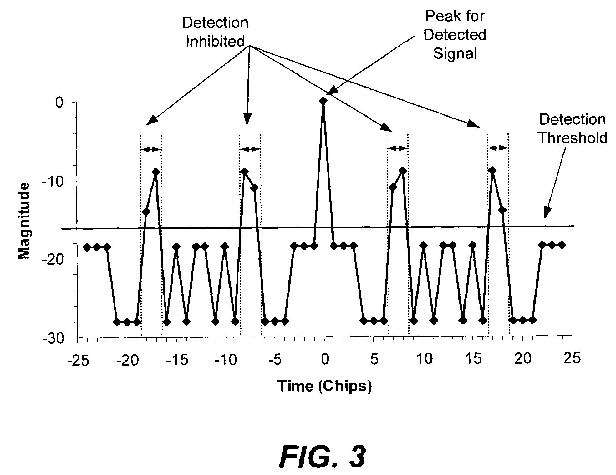
[0012]One embodiment of the invention includes inhibiting the declaring of a signal presence for signal parameter offsets from a detected signal corresponding to known sidelobe locations of the spreading code. For example, signal parameter offsets can include code phase differences, code frequency differences, and signal frequency differences. Inhibiting the declaring of a signal presence caused by a sidelobe can help to reduce false detections.

Problems solved by technology

Unfortunately, there are few codes which have this ideal autocorrelation, and even those codes which are close to ideal often have other aspects which are undesirable (e.g., complexity or limited code length).
For various reasons, many systems use non-ideal codes which have autocorrelation sidelobes.
For example, when searching for a spread spectrum signal by performing correlation, it can be difficult to distinguish a sidelobe from the actual correlation peak.
False detections are undesirable because it is generally not possible to detect message data since the sidelobe does not correspond to correct alignment between the reference code and the spread spectrum signal.
False detections tie up resources, and thus are undesirable.

Method used


Image

  • Spread spectrum signal detection with inhibiting for known sidelobe locations
  • Spread spectrum signal detection with inhibiting for known sidelobe locations
  • Spread spectrum signal detection with inhibiting for known sidelobe locations

Examples


Embodiment Construction

[0022]Reference will now be made to the exemplary embodiments illustrated in the drawings, and specific language will be used herein to describe the same. It will nevertheless be understood that no limitation of the scope of the invention is thereby intended. Alterations and further modifications of the inventive features illustrated herein, and additional applications of the principles of the invention as illustrated herein, which would occur to one skilled in the relevant art and having possession of this disclosure, are to be considered within the scope of the invention.

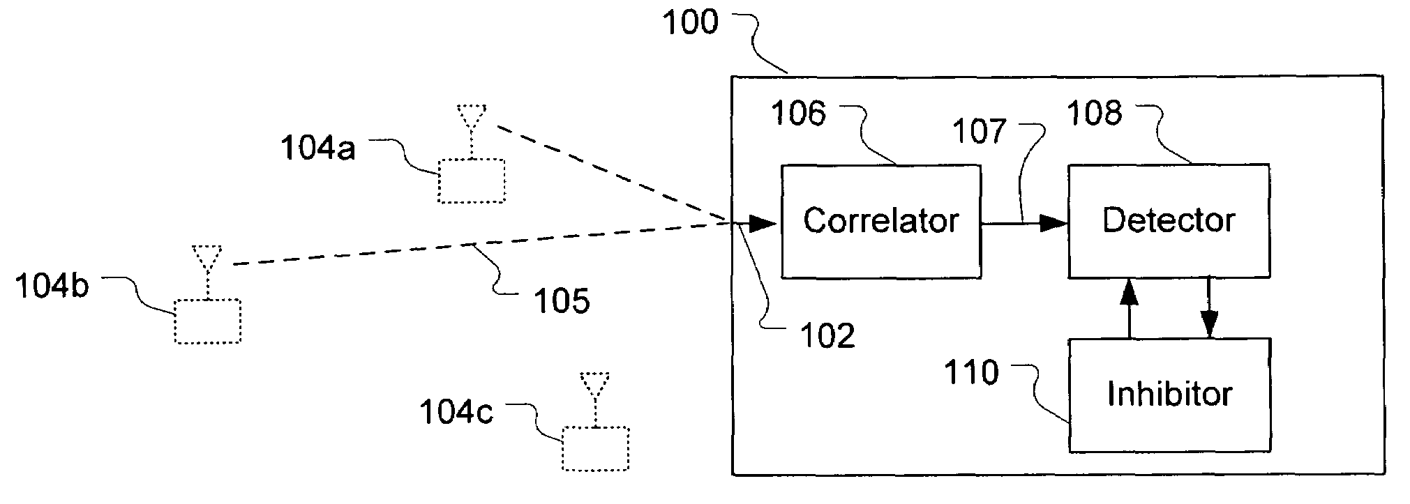
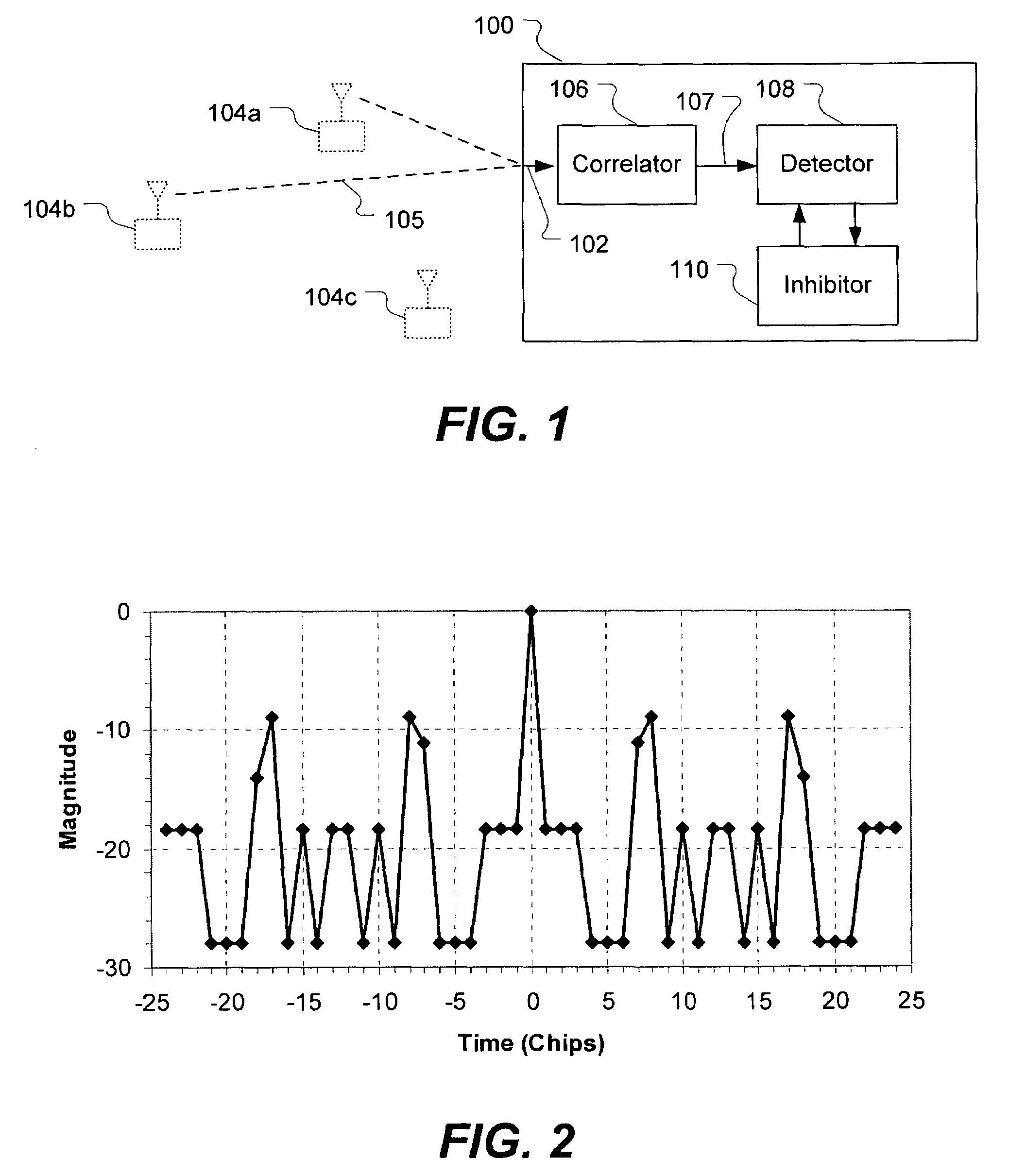
[0023]FIG. 1 illustrates a system for detecting a spread spectrum signal. The system, shown generally at 100, accepts a received signal 102 in which the spread spectrum signal may be embedded. The spread spectrum signal has a predefined spreading code, and may originate from one of several different transmitters. For example, transmitters 104 may transmit radio signals 105 to the system via a wireless communicatio...


PUM


Abstract

A method and apparatus for detecting a spread spectrum signal is described. Signals can be detected using correlation techniques. When a signal is detected, declaring of signal presence is inhibited for offsets of signal parameters from the parameters of the detected signal, where the offset corresponds to a known sidelobe of the spreading code. This helps to reduce false detections caused by sidelobes of the spreading code.

Description

FIELD OF THE INVENTION[0001]The present invention relates generally to detection of spread spectrum signals. More particularly, the present invention relates spread spectrum signal detection where signal presence declaration is inhibited for offsets corresponding to known sidelobes of the spreading code.BACKGROUND[0002]Spread spectrum techniques have proven useful in a variety of communications applications, including cellular telephones, wireless local area networks, and military communications. Wireless spread spectrum systems operate by using a relatively large amount of spectrum bandwidth to communicate messages. The large bandwidth is consumed by spread spectrum encoding the message data using a pseudonoise code. The two most common types of spread spectrum transmission are frequency hopping, where the pseudonoise code is used to pseudo randomly change the transmission frequency on a periodic basis, and direct sequence, where the pseudonoise code is used to sequentially modulat...

Claims


Application Information

Patent Timeline
IPC IPC(8): H04B1/00
CPCH04B1/7093H04B1/7117
Inventor GIALLORENZI, THOMAS R.LAKE, MATTKINGSTON, SAMUEL C.HARRIS, JOHNNY M.
Owner L3 TECH INC
Why Eureka
Eureka Blog
Learn More