
Architecture for efficient utilization and optimum performance of a network

a network and network technology, applied in data switching networks, multiplex communication, digital transmission, etc., can solve problems such as congestion and delay, critical bandwidth shortages across many networks, and exceed the amount of bandwidth available, so as to ensure network transparency, save bandwidth, and improve performance

Inactive Publication Date: 2009-12-29
F5 NETWORKS INC
View PDF46 Cites 79 Cited by
  • Summary
  • Abstract
  • Description
  • Claims
  • Application Information

AI Technical Summary

Benefits of technology

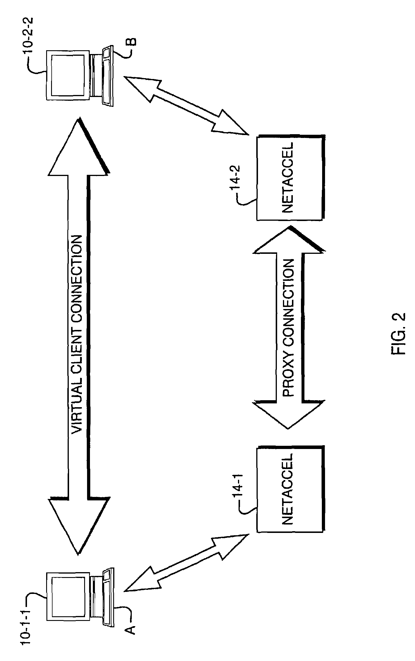
[0010]The present invention provides an architecture for a network optimization computing device that provides bandwidth saving and performance boosting over constrained Wide Area Network (WAN) links. The network acceleration device is positioned at each one of at least two edges of a constrained WAN link. The device intercepts outgoing Internet Protocol (IP) packets, rerouting them to a proxy application on the same device. The proxy application uses a persistent connection with a proxy application located within a corresponding network accelerator device at the other end of the WAN link. The persistent connection is used to transmit the intercepted data after compressing it using a dictionary-based compression algorithm. The device uses techniques such as address spoofing and a proxy-to-proxy communication protocol to assure network transparency from the perspective of the client matrices, so that they do not have to install or run any special application software.
[0012]This architecture provides a number of benefits for network optimization as compared to traditional packet based compression schemes.
[0013]To begin with, most other approaches concentrate on reducing the number of bytes each particular packet has. The approach of the present invention actually reduces the number of packets. This is because compression occurs at a higher layer than the TCP / IP layer, and the compressed stream is divided at inter-packets at the TCP layer. This technique thus results in a smaller number of “fat” or full packets to be transmitted over the LAN link, rather than a large number of “thin” or small packets.
[0015]By reducing the overall number of packets network utilization is actually increased. This reduces the need for packet retransmissions due to errors, in turn reducing the load or routers in the WAN. As a result, a significant boost in the performance of applications running over the WAN is realized.
[0017]Since the architecture results in a significant reduction in the number of packets, sophisticated compression algorithms can be used with essentially no effect on the overall performance. Packet-based compression schemes are typically quite sensitive to the complexity of the compression algorithms employed, and tend to use relatively easy to implement and simple compression schemes. However, the significant packet reduction available with the present invention justifies using complex compression schemes, since the gain more than compensates for the extra processing time.
[0019]Finally, the invention employs a persistent dictionary for every persistent connection. Thus, all connections relevant to a particular type may have a common context. The dictionary thus becomes more or less like a cache for particular traffic types. For example, emails originating from a particular site may have the same fixed header or a trailer containing a confidentially notice. When these emails are sent from different client computers but all originating from the same end of a WAN connection, they will have many words in common. The application of a persistent common dictionary to the persistent connection between the two ends of the WAN link therefore results in efficient compression for the traffic, which is repeatedly sent between the two ends, regardless of the client computer from which it originates.

Problems solved by technology

The growth in data communication traffic, including email, client / server applications, multimedia applications, Internet and intranet applications, has continued to cause critical bandwidth shortages across many networks.
This demand for instant data communication often exceeds the amount of bandwidth available, resulting in congestion and delay.
As more applications move from Local Area Networks (LANs) to Wide Area Networks (WANs) application performance and response time issues become critical to continued smooth operation of an enterprise.
With offices widely distributed around the globe and present day budgetary constraints, the implementation of additional wide area links is cost prohibitive for many international installations.
Since they are not capable of detecting repetition of entire packets or repetitions that exist across multiple packets, they typically may miss many possible repetitions and therefore do not yield a high degree of reduction.

Method used


Image

  • Architecture for efficient utilization and optimum performance of a network
  • Architecture for efficient utilization and optimum performance of a network
  • Architecture for efficient utilization and optimum performance of a network

Examples


Embodiment Construction

[0025]A description of preferred embodiments of the invention follows.

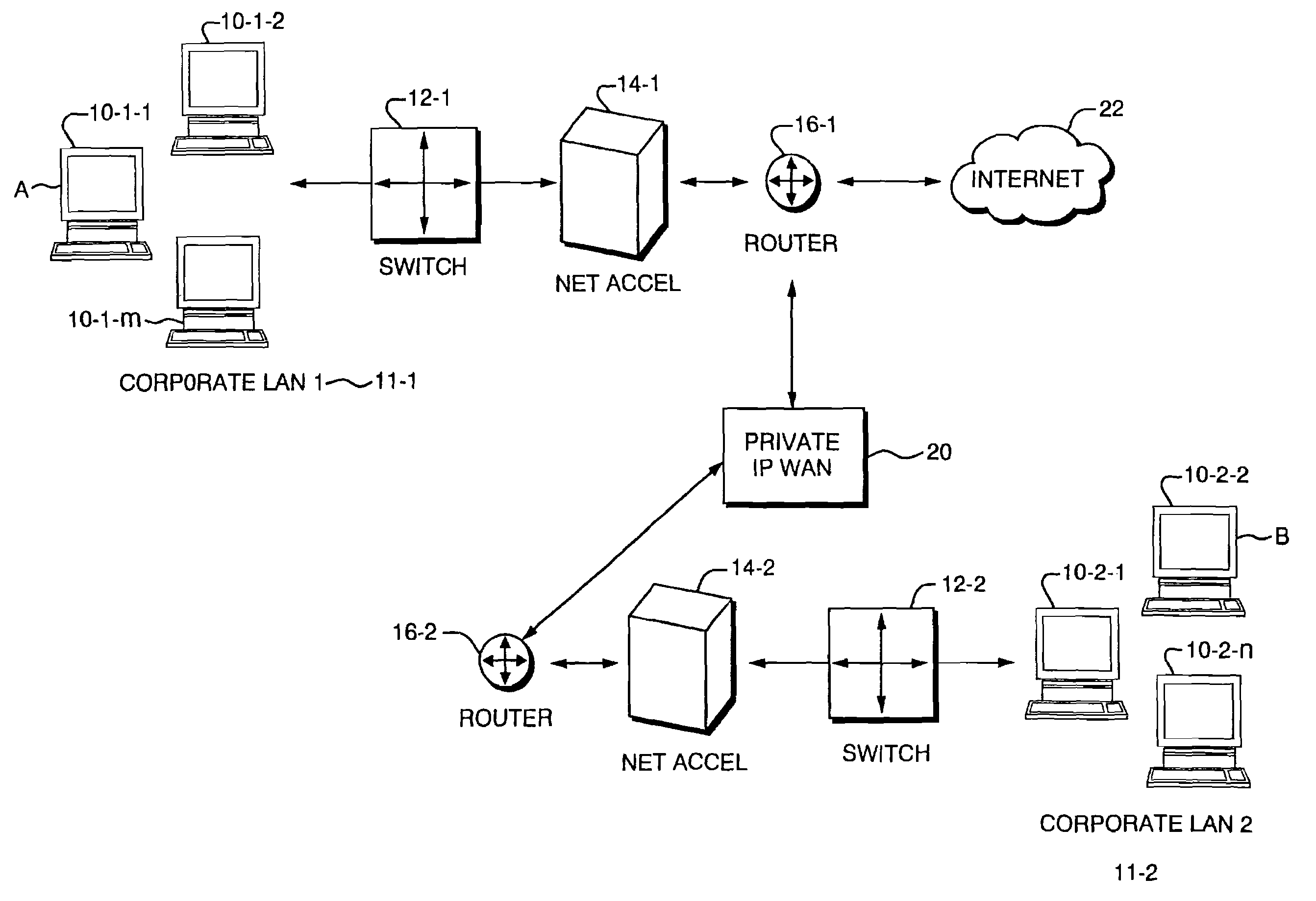
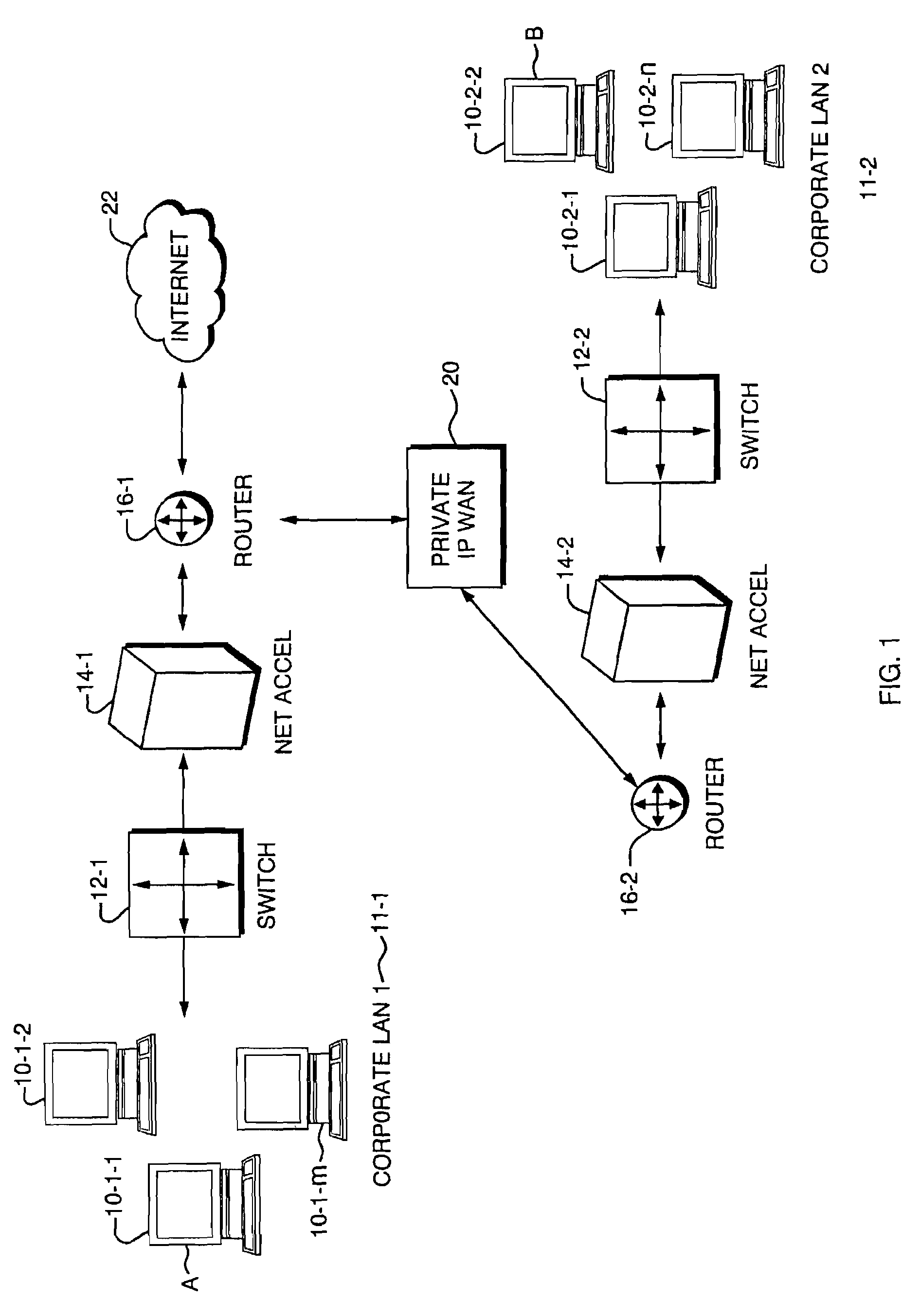
[0026]To achieve the desired performance improvement the present invention employs a network accelerator device (NET ACCEL) 14 at each end of a constrained Wide Area Network (WAN) connection. In the example in FIG. 1, improved communication is to be provided between a first or Local Area Network (LAN) 11-1 and a second LAN 11-2. The respective LANs 11 each consist of a number of client computing devices located at network end nodes such as devices 10-1-1, 10-1-2, . . . 10-1-m that comprise the first LAN 11-1, and similar client devices located at nodes 10-2-1, 10-2-2, . . . 10-2-n located within the second LAN 11-2. It is important to note that the devices herein referred to as the “clients”10 are unaware that their traffic is being communicated via the network accelerators 14-1 and 14-2. Traffic passing through the network accelerators 14 is compressed in a way in which is transparent to the end nodes 10 while ac...


PUM


Abstract

An architecture for optimizing network communications that utilizes a device positioned at two edges of a constrained Wide Area Network (WAN) link. The device intercepts outgoing network packets and reroutes them to a proxy application. The proxy application uses persistent connections with a network accelerator device at the other end of the persistent connection. The proxy applications transmit the intercepted data after compressing it using a dictionary-based compression algorithm. Packet mangling may involve spoofing the connection request at each end node; a proxy-to-proxy communication protocol specifies a way to forward an original address, port, and original transport protocol information end to end. The packet mangling and proxy-to-proxy communication protocol assure network transparency.

Description

CROSS-REFERENCE TO RELATED APPLICATIONS [0001]This utility patent application is a continuation of U.S. patent application Ser. No. 10 / 354,438 filed on Jan. 29, 2003, entitled “Architecture for Efficient Utilization and Optimum Performance of a Network,” the benefit of which is claimed under 35 U.S.C. § 120 and further incorporated herein by reference.BACKGROUND OF THE INVENTION [0002]The present invention relates to increasing performance of Wide Area Network (WAN) communications and in particular to a device positioned at both ends of a constrained link that reroutes outgoing packets to a proxy application that implements data compression.[0003]The growth in data communication traffic, including email, client / server applications, multimedia applications, Internet and intranet applications, has continued to cause critical bandwidth shortages across many networks. This demand for instant data communication often exceeds the amount of bandwidth available, resulting in congestion and ...

Claims


Application Information

Patent Timeline
Patent Type & Authority Patents(United States)
IPC IPC(8): H04L12/26H04L29/06H04L29/08
CPCH04L29/06H04L67/2828H04L67/2814H04L69/329H04L67/563H04L67/5651H04L9/40
Inventor NABHAN, TAREKHELMY, YOUSSRI
Owner F5 NETWORKS INC
Learn More