
Fan and motor thereof

a technology of a fan and a motor, which is applied in the direction of positive displacement liquid engines, piston pumps, liquid fuel engines, etc., can solve the problems of reducing the reliability of the electronic device, increasing the heat the electronic device generates, and unstable electronic devices, so as to reduce noise, reduce costs, and different elastics

Active Publication Date: 2009-12-22
DELTA ELECTRONICS INC
View PDF3 Cites 23 Cited by
  • Summary
  • Abstract
  • Description
  • Claims
  • Application Information

AI Technical Summary

Benefits of technology

This design provides improved water-proof and dust-proof protection at a lower cost while also absorbing vibrations, reducing noise, and enhancing heat dissipation, thereby increasing the reliability of electronic devices.

Problems solved by technology

However, the higher the integrity of the electronic element is, the more heat the electronic device generates.
The generated heat may lead to the unstable of the electronic device and thus reduce the reliability of the electronic device.
Consequently, the heat dissipation is an important issue in this industry.
Since these elements are not protected, moisture or dusts in the air may damage and dampen them, or even burn off the circuit.
Accordingly, the electronic device may malfunction.
Although a protective layer coated on the surface of the stator structure is proposed in the prior art to protect the stator structure from water and dusts in the air, the thickness of the protective layer is only a few tens of microns due to the limitation of current technologies and device structures.
Therefore, the protection effect is limited whereas the cost is high.

Method used


Image

  • Fan and motor thereof
  • Fan and motor thereof
  • Fan and motor thereof

Examples


Embodiment Construction

[0018]The present invention will be apparent from the following detailed description, which proceeds with reference to the accompanying drawings, wherein the same references relate to the same elements.

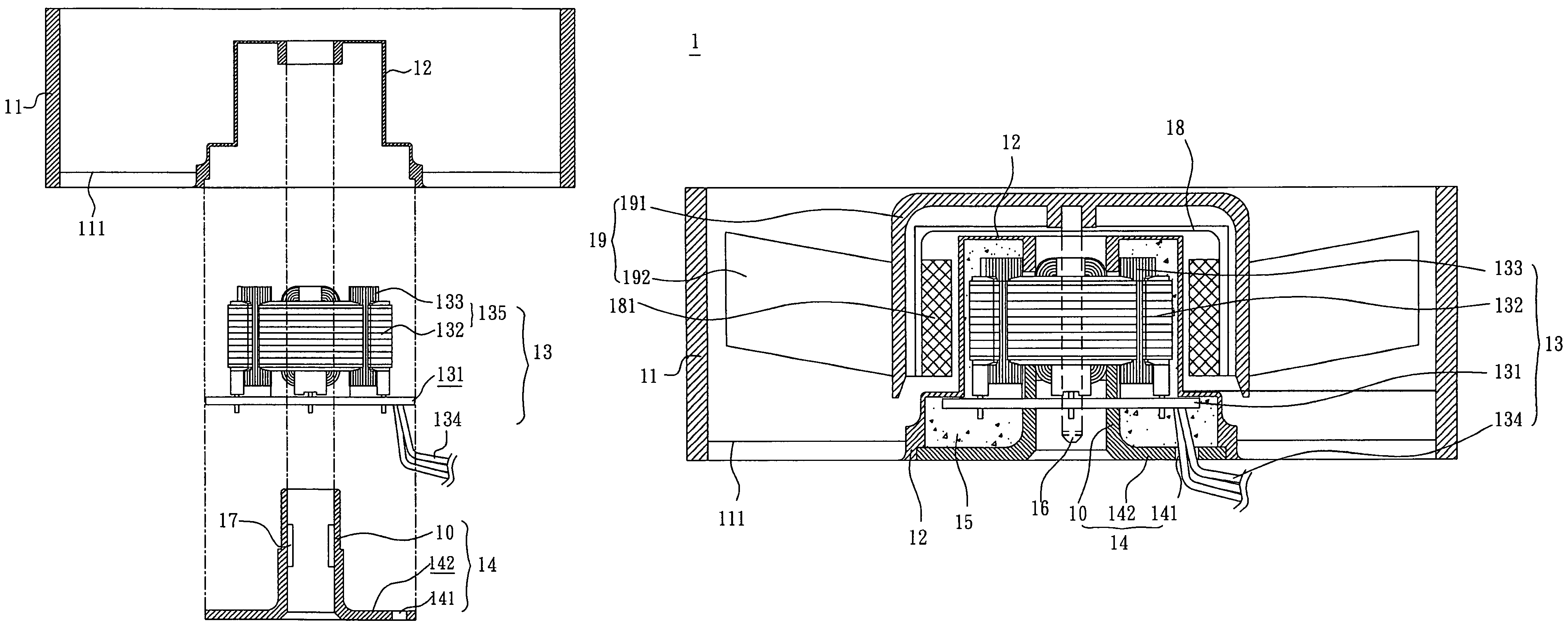
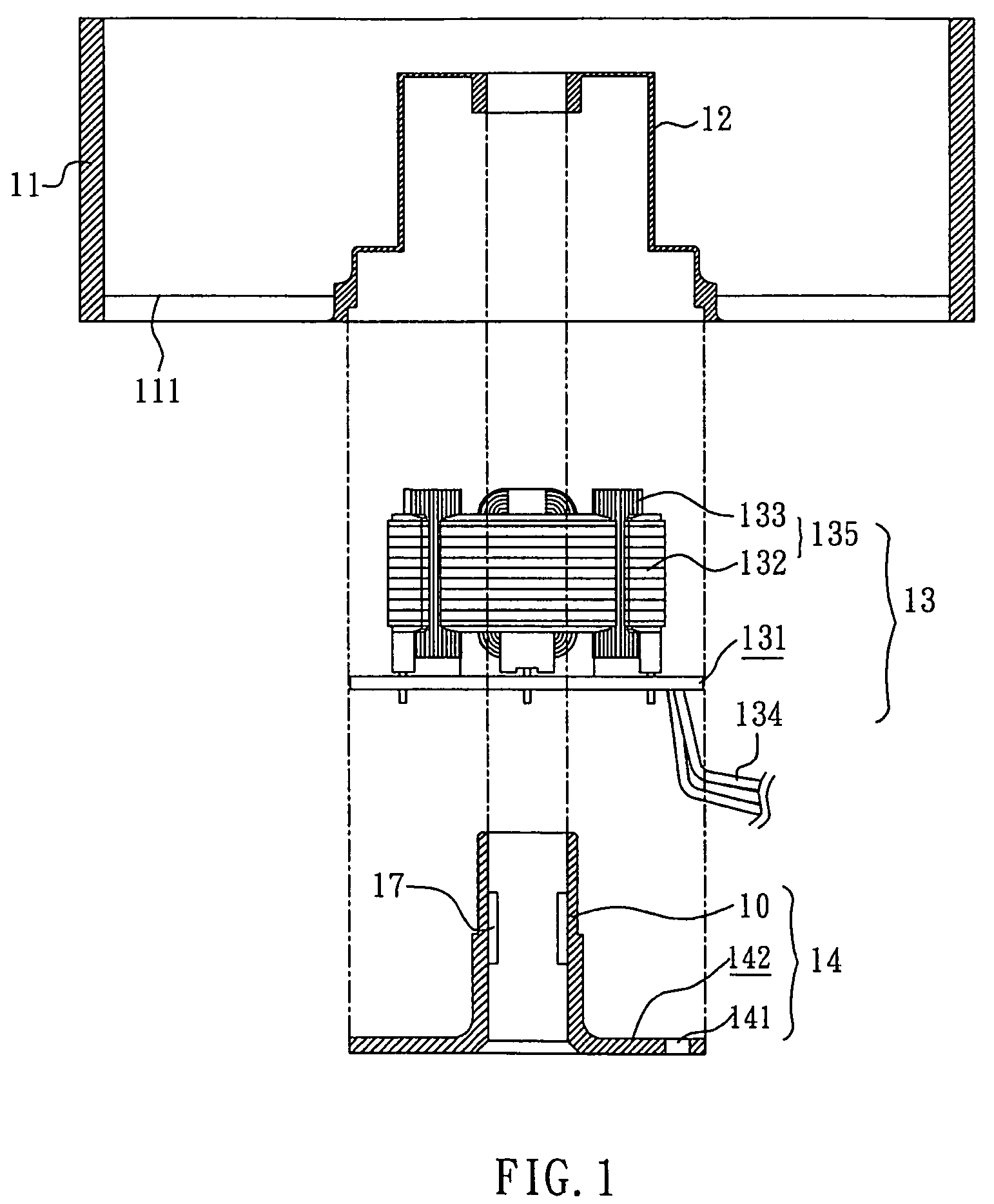
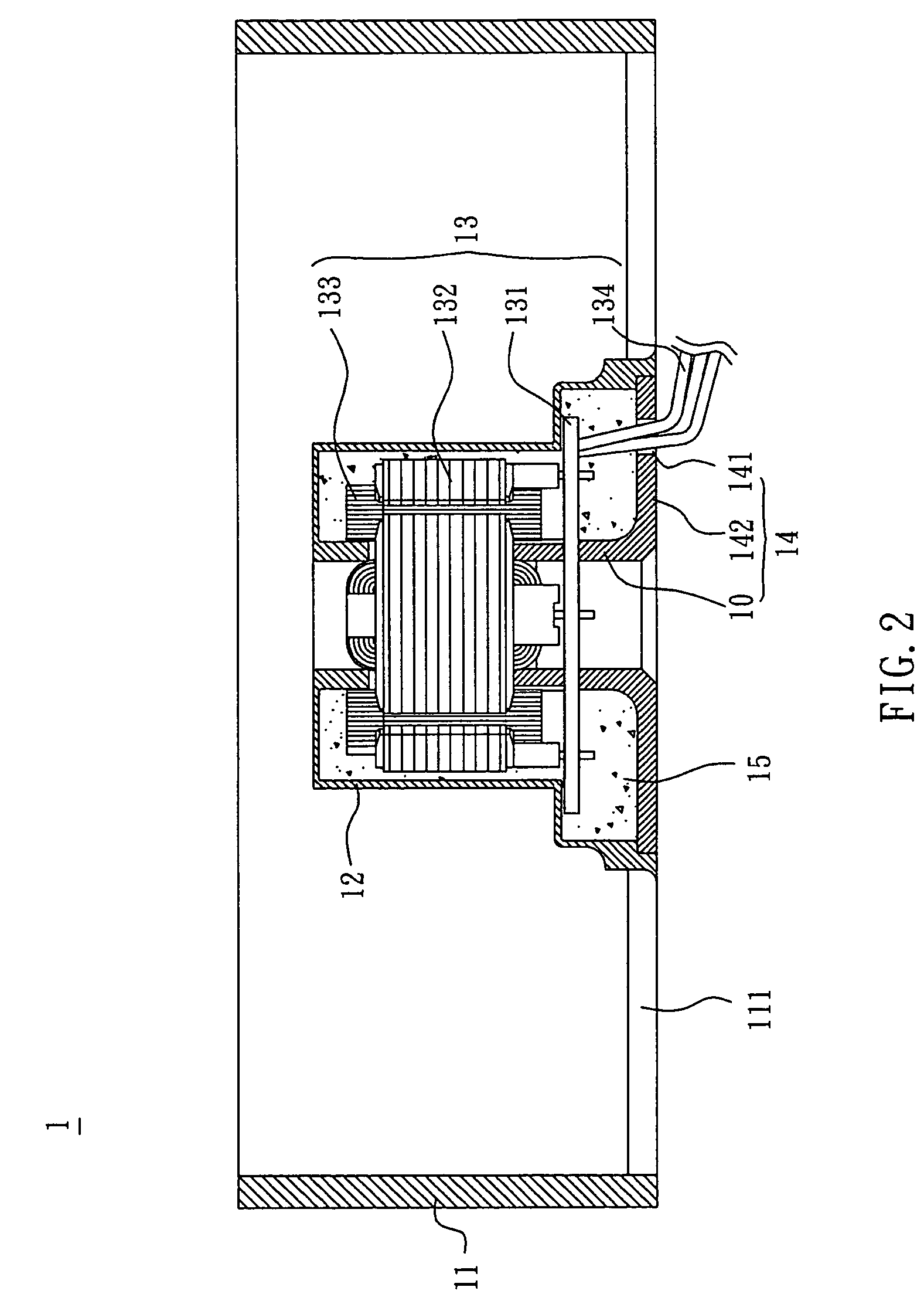
[0019]With reference to FIGS. 1 and 2, a fan 1 according to a preferred embodiment of the invention includes a frame 11, a cover 12, a stator structure 13, and a base 14. The cover 12, the stator structure 13, and the base 14 are some components of a motor. In this embodiment, the materials of the frame 11, cover 12, and base 14 of the fan 1 can be the same or different. For example, the frame, the cover, or the base can be made of a plastic material, an acrylic material, a metal material, an alloy, or a water-proof material.

[0020]The cover 12 is connected with the frame 11 by at least one supporting member 111. The cover 12 and the frame 11 are integrally formed as a single piece. Moreover, the cover 12, the supporting member 111 and the frame 11 may be integrally formed. In this emb...


PUM


Abstract

A fan structure includes a frame, a cover, a stator structure and a base. The cover and the frame are integrally formed as a single piece. The stator structure is disposed in the cover and the base is connected to the cover. Thus, the stator structure is located between the cover and the base.

Description

CROSS-REFERENCE TO RELATED APPLICATIONS[0001]This Non-provisional application claims priority under 35 U.S.C. §119(a) on Patent Application No(s). 094145982 filed in Taiwan, Republic of China on Dec. 23, 2005, the entire contents of which are hereby incorporated by reference.BACKGROUND OF THE INVENTION[0002]1. Field of Invention[0003]The invention relates to a fan and the motor thereof, and, in particular, to a water-proof fan and the motor thereof.[0004]2. Related Art[0005]Accompanying with the development of technology, the electronic devices have a trend toward high-speed, function-integrated, and compactified. However, the higher the integrity of the electronic element is, the more heat the electronic device generates. The generated heat may lead to the unstable of the electronic device and thus reduce the reliability of the electronic device. Consequently, the heat dissipation is an important issue in this industry. In present, a fan is commonly used as a heat-dissipating unit ...

Claims


Application Information

Patent Timeline
Patent Type & Authority Patents(United States)
IPC IPC(8): H02K5/10
CPCF04D29/582F04D29/646H02K15/12H02K11/0073H02K1/187H02K5/08H02K11/33
Inventor ZHU, MICHEASFU, DENG-CHULIN, YUNG-PING
Owner DELTA ELECTRONICS INC
Learn More