Serial radio frequency to baseband interface with programmable clock

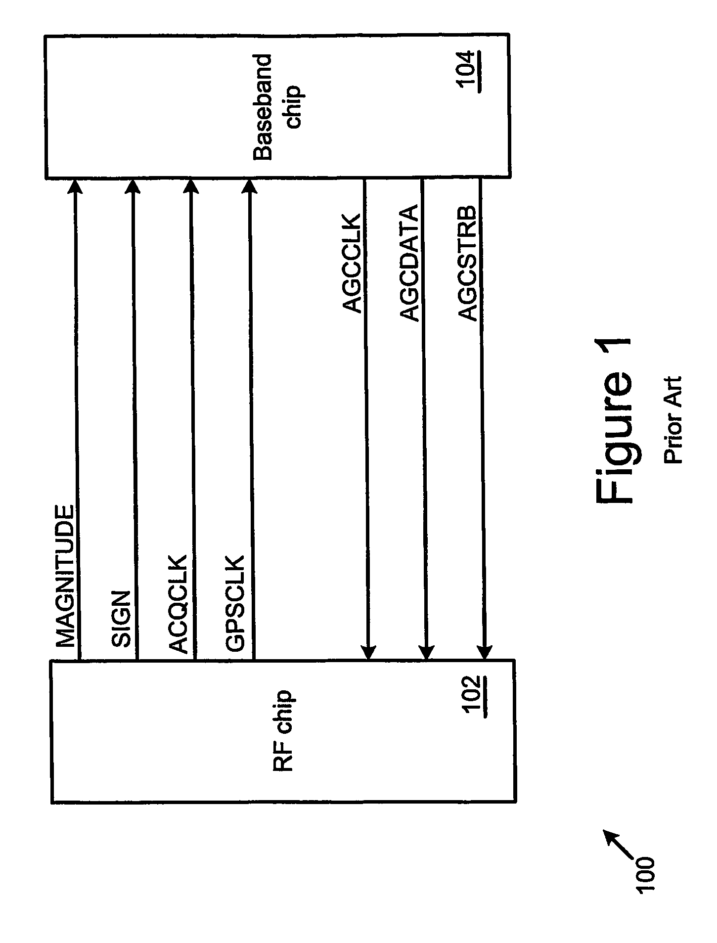
a radio frequency and baseband technology, applied in the field of serial message and data interface between an rf processing section and a baseband processing section, can solve the problems of single purpose unidirectional communication capability between the baseband and rf sections, the pin count and manufacturing cost of the chipset is not known, and the baseband section communicates agc information unidirectionally

Inactive Publication Date: 2009-12-15
CSR TECH INC
View PDF35 Cites 3 Cited by
  • Summary
  • Abstract
  • Description
  • Claims
  • Application Information

AI Technical Summary

Benefits of technology

[0011]The invention provides an interface (and methods of operating or providing interfaces) between an RF processing section and a baseband processing section. The interface supports general purpose bi-directional message transmission between the RF processing section and the baseband processing section. The interface further supports transmission of SPS signal samples between the two processing sections without adding undue complexity to the interface.
[0013]The complexity of the data serial interface may be reduced, for example, by using a single data bit signal line to serially carry signal samples from the RF section to the baseband section. The data serial interface may also include a data clock signal line that provides timing for the signal samples. In particular, as an example, the data clock signal line may carry a data clock (that includes rising edges and falling edges) nominally running at 16 fo, where fo=1.023 MHz, while the data bit signal line may carry a data signal comprising serially transmitted data bits. In one embodiment, a first type of data bit is valid on the rising edge of the data clock and a second type of data bit is valid on the falling edge of the data clock. As an example, the first type of data bit may be a sign bit, while the second type of data bit may be a magnitude bit.

Problems solved by technology

However, the baseband section communicated AGC information unidirectionally to the RF chip using a single pulse width modulated output that the RF chip sampled.
As the number of interface signals grows, so does the pin count and manufacturing cost of the chipset.
Furthermore, only single purpose unidirectional communication capability has existed between the baseband and RF sections.
As a result, the pre-existing chipset are limited in their flexibility and sophistication for incorporation into the widest possible range of devices.

Method used


Image

  • Serial radio frequency to baseband interface with programmable clock
  • Serial radio frequency to baseband interface with programmable clock
  • Serial radio frequency to baseband interface with programmable clock

Examples


Embodiment Construction

[0022]A typical satellite positioning system (“SPS”) system has approximately 12 satellites that may be visible at any one time to a wireless device. As used in this document, SPS means any system utilizing satellites and / or land-based communications devices for providing or enabling the determination of a location of the wireless device on the earth, including, but not limited to: a global positioning system (“GPS”) (such as NAVSTAR), GLONASS, LORAN, Shoran, Decca, or TACAN. For the purposes of discussion, specific examples of an interface between a GPS RF processing section and a baseband processing section are described. However, the principles underlying the interface are applicable to interfacing RF processing and baseband processing sections in general.

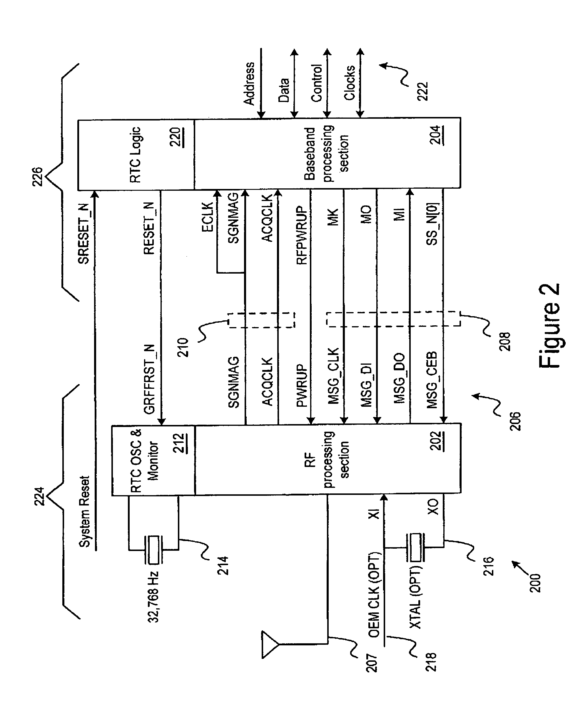
[0023]Turning first to FIG. 2, that figure shows a receiver 200 of a satellite positioning system. The receiver 200 includes an RF processing section 202 coupled to a baseband processing section 204 using an RF-to-baseband inter...


PUM


Abstract

An interface between an RF processing section and a baseband processing section supports general purpose message transmission as well as satellite positioning system signal sample transmission between the RF processing section and the baseband processing section. The interface includes a bi-directional message serial interface and a data serial interface. The complexity of the data serial interface may be minimized by using a single data bit signal line in the data serial interface.

Description

1. CROSS-REFERENCE TO RELATED APPLICATION[0001]This application claims priority to U.S. patent application Ser. No. 10 / 369,853 filed on Feb. 19, 2003.BACKGROUND OF THE INVENTION[0002]1. Field of the Invention[0003]This invention relates to an interface for coupling a radio frequency (RF) processing section to a baseband processing section. More specifically, this invention relates to a serial message and data interface between an RF processing section and a baseband processing section.[0004]2. Related Art[0005]The worldwide use of wireless devices such as two-way radios, pagers, portable televisions, personal communication systems (“PCS”), personal digital assistants (“PDAs”) cellular telephones (also known as “mobile phones”), Bluetooth devices, satellite radio receivers and Satellite Positioning Systems (“SPS”) such as the Global Positioning System (“GPS”), also known as NAVSTAR, is growing at a rapid pace. Current trends are calling for the incorporation of SPS services into a br...

Claims


Application Information

Patent Timeline
Patent Type & Authority Patents(United States)
IPC IPC(8): H04L27/06H04L7/00G01S19/13G01S19/35G01S19/49H04B1/16H04L12/56
CPCH04W88/02H04B1/16H04B1/40H04B1/28H04M1/00
Inventor GRONEMEYER, STEVETSO, ROBERT
Owner CSR TECH INC
Why Eureka
Try Eureka