
Plane antenna

a technology of plane antenna and polarized wave, which is applied in the direction of resonant antenna, polarised antenna unit combination, screened loop antenna, etc., can solve the problems of excellent circular polarized wave characteristics, and achieve the effect of preventing product shoplifting, excellent circular polarized wave, and simplified structur

Inactive Publication Date: 2009-12-15
FUJITSU LTD
View PDF11 Cites 3 Cited by
  • Summary
  • Abstract
  • Description
  • Claims
  • Application Information

AI Technical Summary

Benefits of technology

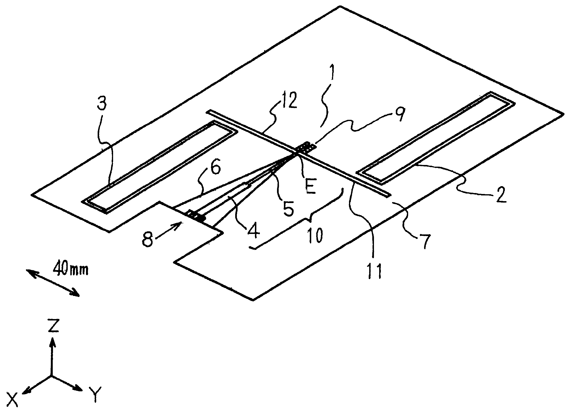
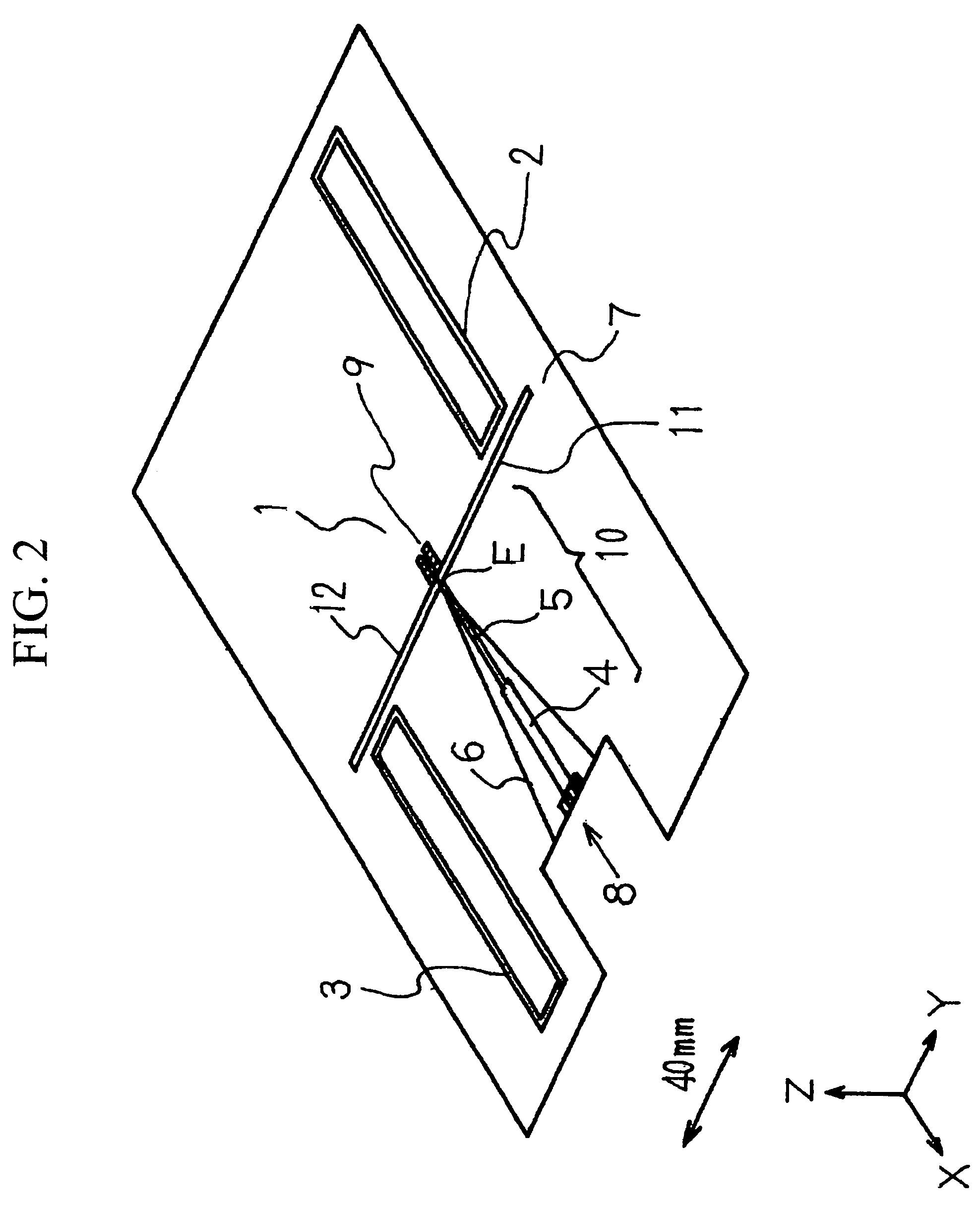
The present invention provides a plane antenna that can attain an excellent circularly polarized wave with a simplified structure. The antenna can be used for various applications such as mobile bodies, book management systems, POS systems, and security systems. The antenna has a dipole antenna formed of a couple of radiating elements and a power feeding pattern connected to the radiating elements. The substrate has first and second surfaces with first and second radiating elements, respectively. The first and second radiating elements form a dipole antenna. An impedance-adjusting unit or an impedance-converting unit can be added to the power feeding patterns. The plane antenna has a simplified structure and can attain an excellent circularly polarized wave.

Problems solved by technology

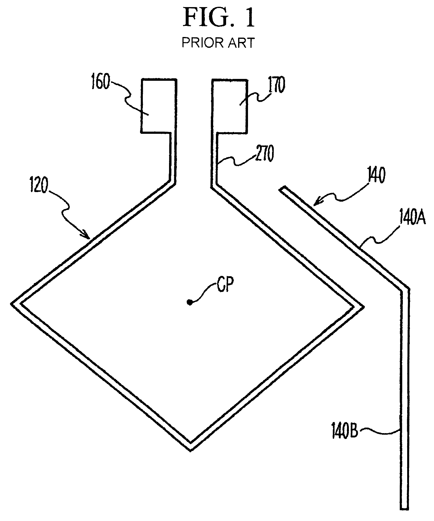
However, it has been difficult for the technology proposed in Japanese Patent Application JP-A 2005-102183 to obtain sufficient circularly polarized wave characteristics because electric field distribution to the non-power feeding element 140 is rather weak due to its structural features.
Namely, Japanese Patent Applications JP-A 2005-72716 and JP-A 1997-260925 are not intended to obtain excellent circularly polarized wave characteristics.

Method used


Image

  • Plane antenna
  • Plane antenna
  • Plane antenna

Examples


Embodiment Construction

[0037]Since the plane antenna of the present invention is constituted as explained above, a circularly polarized wave having excellent characteristic in the vertical direction to both sides of a substrate plane can be generated, sufficient radio waves can be supplied to a tag or the like, and the communication distance can be extended.

[0038]The plane antenna of the present invention can be reduced in size and cost by eliminating circuits such as a balun or an impedance converting circuit, which are components that are different from the antenna even when electrical power is fed with a coaxial cable.

[0039]The plane antenna of the present invention is capable of providing the unbalanced-to-balanced converting unit with a broadband characteristic by shaping the power-feeding pattern to be used to an isosceles triangle.

[0040]The preferred embodiments of the present invention will be explained with reference to the accompanying drawings. However, these preferred embodiments do not restri...


PUM


Abstract

A plane antenna comprises a substrate having a first surface and a second surface, a first radiating element, a first power feeding pattern connected to the radiating element, and a first non-power feeding loop type radiating element provided adjacent to the first radiating element, all disposed on the first surface of the substrate, and a second radiating element, a second power feeding pattern connected to the radiating element, and a second non-power feeding loop type radiating element provided adjacent to the second radiating element, all disposed on the second surface of the substrate.

Description

BACKGROUND OF THE INVENTION[0001]1. Field of the Invention[0002]The present invention relates to a plane antenna and more specifically to the technology suitable for antenna formed on a dielectric material substrate to generate circularly polarized wave.[0003]2. Background of the Prior Art[0004]In recent years, a vehicle (mobile) such as an automobile has often been provided with an antenna for GPS (Global Positioning System) in the high frequency band or an antenna for receiving radio waves from satellites for satellite digital broadcasts. Moreover, it is also required for a mobile vehicle to install an antenna for transmitting and receiving radio waves for the ETC (Electronic Toll Collecting) system for automatically collecting tolls on expressways and toll roads and for radio wave beacons of the VICS (Vehicle Information Communication System) for providing vehicle traffic information.[0005]For the GPS radio wave, satellite wave for satellite digital broadcast and ETC radio wave, ...

Claims


Application Information

Patent Timeline
Patent Type & Authority Patents(United States)
IPC IPC(8): H01Q19/10H01Q9/28
CPCH01Q1/22H01Q1/3233H01Q21/24H01Q9/16H01Q7/00H01Q1/2225H01Q1/38H01Q7/04H01Q9/285
Inventor YAMAGAJO, TAKASHIMANIWA, TORUANDRENKO, ANDREY
Owner FUJITSU LTD
Learn More